This article is intended to serve as a guide in the development of equipment layout and piping layout for centrifugal compressors and their associated equipment, with the goal of producing safe, operable, economical, and maintainable installations.
Compressors are machines, which are used to increase the pressure of a gas by mechanically reducing its volume within the compressor casing.
Compressor Types
Positive Displacement Compressors
Reciprocating compressor
Screw Compressors
Centrifugal compressors
Pipeline compressors
Type of Compressor Drives
Following are the various types of Compressor drives:
Electric Motor Drives
AC Squirrel Cage Induction Motor
Synchronous AC Motor
Gas Turbines
Steam Turbines
Variable Speed Drives
Variable Frequency Drive
Variable speed (Hydraulic Coupling) Drives
Auxiliary Equipment’s
Lube Oil Cooler (Supplied by Compressor Vendor)
Lube Oil / Seal Oil Console (Supplied by Compressor Vendor)
Surface Condenser
Condensate Pump
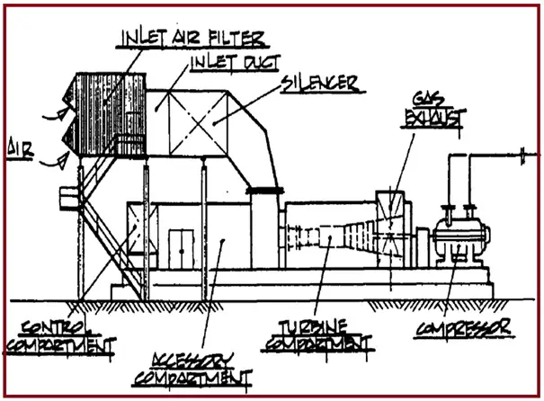
Inlet Air Filters (Supplied by Compressor Vendor)
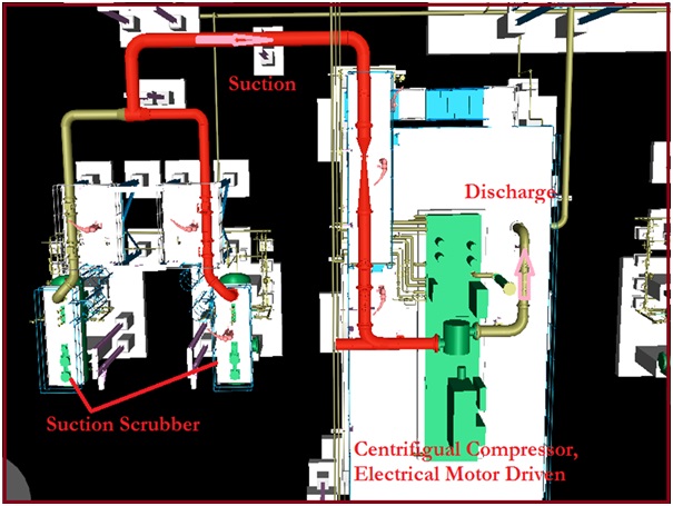
Suction Scrubber (Upstream of Compressor)
Air Cooler (Downstream of Compressor)
Discharge Scrubber (Downstream of Air Cooler)
Compressor Layout
When locating compressors, consideration must be given to accessibility, maintenance, and loss prevention requirements.
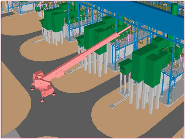
There must be a Vehicular (Crane / Fork Lift Truck) Access-way on at least one side of the installation. Refer Fig. 1
Fig. 1: Figure showing the requirement of Crane Access
A compressor is generally located inside Shed with the provision of a Mono-Rail or EOT Crane for Maintenance. The capacity of the crane is to be decided based on 150% of the highest weight of the component to be lifted. To be checked with the compressor vendor.
A compressor can be installed in a Series and Parallel arrangement.
The minimum Distance between two Adjacent Compressors shall be 10m.
Generally, Compressors are Grade Mounted (Fig. 2). But Process criteria/requirements will decide if it should be grade mounted or elevated
Fig. 2: Grade-mounted Centrifugal Compressor
Compressor Piping Layout
Suction & Discharge Piping (Fig. 3)
Compressor Suction Piping Shall be as Short as Possible.
Compressor Suction Piping should have Inlet Filter / Strainer. It can be Temporary or Permanent
Suction Piping should be sloping/free draining towards Inlet Scrubber
Suction lines require a minimum straight run of piping upstream of the suction nozzle which varies between 3 and 8 times the normal pipe size. (Vendor requirement)
All operating valves must be readily accessible, preferably from grade.
All lines to the Compressor shall be provided with break-up flanges for Maintenance.
Compressor Suction Line Flowmeter: Suction routing shall be such that Upstream and Downstream straight lengths shall be sufficient for the performance of the Flowmeter
Anti-Surge Valve Is Designed and Supplied by Compressor Vendor.
Input to Compressor Vendor for Designing / Sizing the Anti-Surge Valve is given by piping, by providing suction and discharge length.
Anti-Surge Valve is located on the Anti-Surge line which is basically a by-pass / recirculation line between Compressor Suction and Discharge Piping for Surge control
Anti-Surge Valve shall be located at Highest Point and shall be free draining on both side
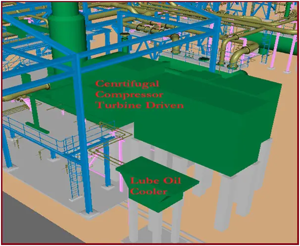
Lube Oil Cooler Shall be located as close to Compressor as Possible.
Lube Oil Cooler Piping Should Not Interfere with Access and Maintenance space.
Lube Oil Cooler line must be Free Gravity flow requirements.
Lube Oil Cooler Piping Should have Break-up Flanges for Maintenance purposes.
Lube Oil Cooler Isometric should also have noted for “Pickling and Passivation” i.e. Chemical cleaning of Lines before commissioning.
Supporting Compressor Piping
The first support from Compressor Suction and Discharge nozzle is either Spring support or Adjustable support for Alignment during Construction / Erection.
Fig. 4: Lube Oil Cooler
Compressor piping should never be supported by the Compressor foundation. Pipe supports must be provided with independent foundations to avoid transmission of vibration.
Compressor Suction / Discharge Piping should be routed in such a way that it has enough flexibility to accommodate Thermal Expansion and Reduce the Nozzle Load.
Compressor Suction / Discharge Piping should be adequately supported as per Stress Engineers’ Support requirements.
Process Should be consulted for any possibility of two-phase flow/slug flow and the line should be supported accordingly
As compressors are meant for Gaseous fluid, the Hydro-test load on supports may be very high for big bore lines. Hence we can recommend Temporary supports to be erected during Hydro-testing with the help of a Stress Engineer.
I am a Mechanical Engineer turned into a Piping Engineer. Currently, I work in a reputed MNC as a Senior Piping Stress Engineer. I am very much passionate about blogging and always tried to do unique things. This website is my first venture into the world of blogging with the aim of connecting with other piping engineers around the world.
2 thoughts on “Compressor Piping Layout: Compressor Piping Design”
You should put your piping system design work into a publication like the piping guide. Addition of stress analysis with a program like Caesar 2 would be a great addition to the guide.
The remarkable corrosion resistance of Fe-Cr-Ni-Mo stainless steel in dilute acidic environments containing trace chlorides has been well-known over the years. The corrosion resistance arises because...
Subsea pipelines play a critical role in transporting oil and gas (hydrocarbon) from remote exploration and production sites to processing facilities and ultimately, consumers. They are essential...


You should put your piping system design work into a publication like the piping guide. Addition of stress analysis with a program like Caesar 2 would be a great addition to the guide.
Great work and Thankyou