Centrifugal compressors are widely used in process plants to compress gases. Centrifugal Compressors, being rotary equipment, are highly sensitive and prone to vibration. So, the connected piping system must be designed with care to get optimum performance. In this article, we will explore the design of centrifugal compressor piping and appurtenances.
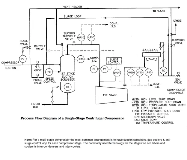
Fig. 1: Process Flow Diagram of a Single-Stage Centrifugal Compressor
The surge control or anti-surge system shown in the above PFD is a very basic representation of the system. There are many variations to the basic representation shown in the PFD including the measurement of temperature at suction and discharge providing feedback to the anti-surge system.
The design considerations for the centrifugal piping are divided into two parts.
Suction Piping Design Considerations and
Discharge Piping Design Considerations
Centrifugal Compressor Suction Piping Design
Process Considerations for Suction Piping Design
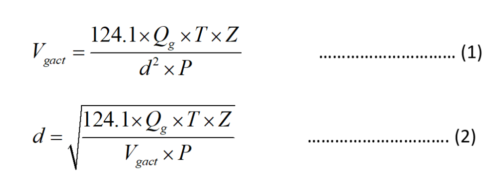
The rule of thumb is to size the suction piping of the compressor’s first stage such that the pressure drop should not exceed 3.4 kPa or 1% of operating pressure (whichever is smaller), and a maximum actual velocity of 9.1 m/sec. To determine the velocity, use the formula provided in Eqn. 1, and to determine the pipe’s internal diameter based on the maximum velocity rule of thumb use the formula provided in Eqn. 2 of Fig. 2 below.
Fig. 2: Formula for Centrifugal Compressor Suction Pipe Diameter Calculation
Where
Vgact = actual gas velocity, m/s
T = gas temperature at suction, K
d = Pipe ID, mm
P = Pressure, kPa (abs)
Qg = gas flow rate, Sm3/h (Note: Sm3/h flow rate is at 15⁰C and 101.325 kPa(abs))
Z = gas compressibility factor at T, P
Piping Considerations for Suction Piping Design
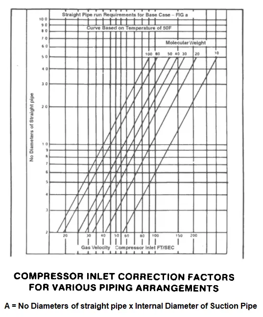
1. Straight Length Requirement
The following figures (Fig. 3 & Fig. 4) establish the practice for straight length ahead of the inlet or suction nozzle of the compressor. The sketch is applicable for multistage compressors including the inlet or suction piping of the subsequent stage after the first stage. The sketch is for the base case for the suction piping provided with one long radius elbow (plane parallel to the rotor). For cases other than the base case various multipliers are used to define the straight length of pipe required ahead of the suction nozzle. All the other cases are also discussed as a subset of the base case using the multipliers:
Fig. 3: Compressor Inlet Correction Factors for various Piping Arrangements
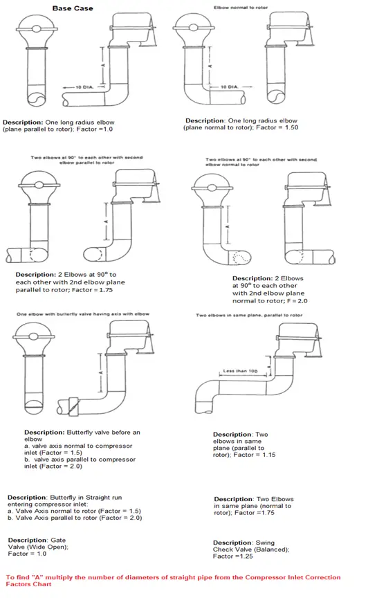
Fig. 4: Various Piping Configurations for Compressor Suction
When suction piping straight length for axial or single-stage compressors needs to be found, the straight length obtained based on the above figures for the various piping arrangement cases shall be multiplied by an additional factor of 1.25.
2. Slope of Compressor Suction Piping
Piping shall slope continuously downward from the suction scrubber to the compressor suction connection. A desirable configuration for the slope of the suction piping would be to provide a slope from the upstream flange of the suction line isolation valve towards the suction scrubber and a slope towards the compressor suction nozzle from the downstream of the suction line valve. Valves shall be located only in horizontal piping.
The provision of suction strainers is mandated in most applications to trap any solid particles that can cause damage to the compressor internals. Screens and Filters used shall have high mechanical integrity and strength to prevent their failure and entry into the compressor casing. All strainers shall be installed as close to the compressor as feasible.
When temporary suction strainers are used, pressure gauge taps shall be provided upstream and downstream for the commissioning of the compressor. When the temporary strainers are removed, the tapped connections shall be plugged, and seal welded.
4. Low Point Drain
Compressors having a suction nozzle orientation such that the suction line connects from the bottom forming a low point in the suction line shall be provided with a small boot or sump with a local gauge glass and a local drain connection to drain any condensed liquid. The boot or sump shall be provided as close as feasible to the compressor suction nozzle and at the lowest point in the suction piping.
5. Lube & Seal Oil System
Hose connections shall not be used in lube and seal oil systems of compressors.
Centrifugal Compressor Discharge Piping Design
Process Considerations for Discharge Piping Design
The interstage and discharge piping thumb rule for sizing is a pressure drop not to exceed 2 percent of operating pressure or 34 kPa (whichever is higher) and a maximum actual velocity (adjusted for temperature and compressibility) of 15.2 m/sec.
Equations 1 & 2 (Fig. 2 above) can be used for evaluating the velocity for a given diameter and the discharge pipe diameter based on the aforementioned maximum velocity.
Maximum velocity considerations are also based on noise criteria observed in gas lines.
Many operators of natural gas transmission pipelines have concluded that velocities up to 20 m/s are acceptable with due consideration of noise. Companies like Shell recommend velocities of 5-10 m/s for continuous operation in long-distance natural gas pipelines and a maximum of 20 m/s for intermittent operation.
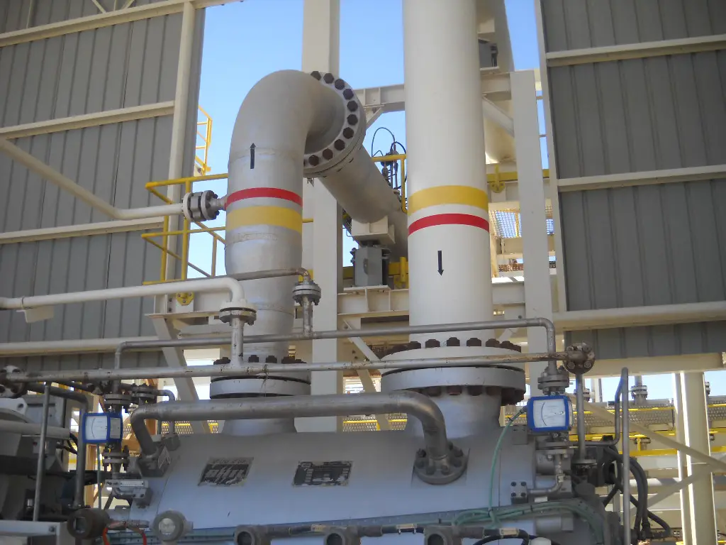
Fig. 5 below shows a typical centrifugal compressor piping system.
Fig. 5: Typical Centrifugal Compressor Suction and Discharge Line
Other Important Design Considerations for Centrifugal Compressor Piping System
Minimum Line Sizes & End Connections
Normally line sizes below 2” are avoided. Threaded connections are not used due to pressure and temperature considerations. For hydrocarbon and other flammable/toxic gases, threaded connections are strictly prohibited. Most designers prefer to use Schedule 80 pipes in high-pressure gas compression applications.
Suction Isolation Valve
For isolating the compressor suction a suction isolation valve is provided in the suction piping which is manually operated. The valve location shall be evaluated on a case-to-case basis. For large-size valves, the manual valve is provided with a gear operator for ease of operation.
For isolating the compressor discharge a discharge isolation valve is provided in the discharge piping which is manually operated. The valve location shall be evaluated on a case-to-case basis, with the general objective of locating it as close as possible to the discharge connection. For large-size valves, the manual valve is provided with a gear operator for ease of operation.
Discharge Check Valve
The check valve prevents reverse flow and reverses the rotation of the compressor unit which can cause serious damage to the seals and bearings. Install the check valve as close as possible to the discharge nozzle considering all aspects of accessibility and maintainability.
Blowdown Valve
The function of the blowdown valve is to relieve the high-pressure gas trapped in the compressor system during a breakdown or a planned shutdown. Most operators use automatic blowdown valves to reduce the hazards of trapped gas. If the blowdown valve has been tied into a closed vent system to route gas to a safe area for flare or vent, a second separate blowdown valve may be required. This valve should vent directly to the atmosphere, with nothing else tied into its line. This practice prevents backflow from the closed vent system while the compressor is down for maintenance and permits small leaks of gas from the compressor to vent safely. The Process Flow Diagram flowsheet shows a manual valve to accomplish this. Occasionally, a three-way valve is used for this purpose.
Flare Valve
As suction pressure increases, the head requirement will decrease, and the gas flow rate will increase. The increased flow rate beyond the design maximum may force the compressor to operate in the stonewall region, which would result in damage to the machine, or it may create too high a power demand for the driver. To avoid these possibilities, a flare valve tied to the vent header is installed at the suction side of the compressor. The valve is operated by a pressure controller, which is attached to the suction line upstream of the suction scrubber. The flare valve will also open if the compressor shuts down, allowing the operator time to react before the process must be shut in.
Flaring or venting may be reduced by installing a control valve in the suction line (not shown in the PFD illustrated). This valve regulates either flow or pressure to avoid operating the compressor in the stonewall region or overloading the driver. As this valve begins to throttle flow into the compressor, pressure will begin to increase in the upstream equipment. If the high flow condition persists, the flare valve will eventually open. However, if the upstream equipment is rated for a high enough pressure and there is a large enough difference between the throttle valve and flare valve set pressures, it is possible that surges of gas can be processed without flaring.
An ESDV is an actuated valve with generally a full close action designed to stop the flow of a hazardous fluid in the enclosed system or prevent loss of containment to the external environment, upon the detection of a dangerous event. The ESDV thus acts to mitigate any catastrophic damage to equipment and the environment. In many cases, an ESDV by its action can prevent injury or loss of life due to a catastrophic event or accident.
Quarter-turn valves are the most common ESD valves for actuation. They can be hydraulically, pneumatically, or electrically operated.
Centrifugal compressors in all sizes shall have a remote-operated emergency shutdown valve in the suction piping. The compressor suction isolation valve, if remotely operated, can also be the emergency shutdown valve. For field operation of the ESDV, a pushbutton station with a position indicator shall be located in the area of the compressor, at least 15m away, and in a location that is easily accessible. Location consideration shall also take into account that the pushbutton station is not exposed to fire. The remotely operated ESDV shall also be operable from the central control room.
Fireproofing of remote-control emergency shutdown valve assemblies is required. All resilient seated emergency shutdown valves shall be of a fire-safe design.
Silencers (as required)
Silencers are required to suppress the intake noise from compressors which is generated by the high-speed rotation of the impeller(s). They may be installed as per the application on a case-to-case basis. Silencers shall be located as close as possible to the suction and discharge nozzles as feasible. On the discharge side, the silencer is required to be located downstream of the check valve. To optimize the layout, the silencers may be arranged with side or end connections. Silencer shells and flanges shall conform to the piping class and specifications of the respective piping they are connected with.
Ankur Srivastava is a Chemical Engineer with 35 years of process engineering experience in oil and gas, refining, polymers, and petrochemical industries. His vast experience includes conceptual and feasibility studies, front end engineering design, detail engineering, company standards preparation, pre-commissioning / operation manuals, erection, pre-commissioning, and start-up assistance, PHA and HAZOP, and planning and quality control. He runs a blog on an American website “Cheresources” titled “Ankurs Chemical Engg Blog” with a viewership exceeding 2 million for his blog articles. He also contributes to chemical engineering articles on other popular professional and engineering platforms such as LinkedIn & whatispiping.com
The remarkable corrosion resistance of Fe-Cr-Ni-Mo stainless steel in dilute acidic environments containing trace chlorides has been well-known over the years. The corrosion resistance arises because...
Subsea pipelines play a critical role in transporting oil and gas (hydrocarbon) from remote exploration and production sites to processing facilities and ultimately, consumers. They are essential...

? Purpose, Symbols, Examples, & Development of Process Flow Diagram")


