
Introduction: The Silent Threats Beneath Your Infrastructure
Millions of miles of pipelines operate unseen, transporting critical resources that power modern economies. Yet these critical infrastructure assets face relentless threats. Over time, they become vulnerable to hidden defects—corrosion, dents, stress from ground movement—anomalies that silently compromise integrity and pose significant risks if left undetected.
The Central Question: How do you manage what you cannot see?
The Answer: In-Line Inspection (ILI) technology, combined with rigorous engineering assessment and strategic repair methodologies. Modern pipeline integrity management is a data-driven discipline that transforms uncertainty into actionable intelligence.
Part I: Detection and Inspection
The Cornerstone Technology: In-Line Inspection (ILI)
In-Line Inspection is the foundation of modern Pipeline Integrity Management (PIM). It enables non-destructive examination of internal and external pipeline conditions without interrupting service—a critical advantage for operational reliability.
ILI utilizes autonomous robotic devices, colloquially known as “smart pigs,” equipped with advanced sensor systems. Unlike time-consuming manual inspections with limited coverage, ILI provides continuous assessment across extensive pipeline systems, from small-diameter lines to those exceeding 56 inches.
The Three Core Questions of Any Integrity Program
Every integrity program must answer three fundamental questions:
1. Is it damaged? (Geometry)
- Are there dents, restrictions, or other deformations that compromise the pipe’s structure?
- Mechanical damage remains a leading cause of pipeline failures.
2. Where is it? (Mapping)
- What is the pipeline’s precise 3D location?
- Ground movement, soil instability, and external forces can shift the pipe, inducing dangerous stress and strain.
3. Is it corroding? (Metal Loss)
- Is the pipe wall thinning due to corrosion or other metal loss mechanisms?
- Even small defects can grow into critical threats over time.
The Inspection Process: A Systematic Three-Stage Approach
The ILI process follows a well-established sequence:
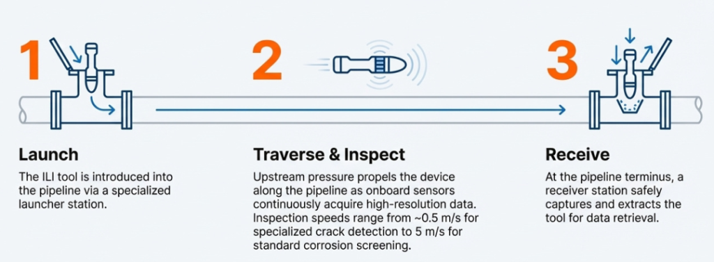
Stage 1: Launch
- The ILI tool is introduced into the pipeline via a specialized launcher station.
Stage 2: Traverse & Inspect
- Upstream pressure propels the device along the pipeline as onboard sensors continuously acquire high-resolution data.
- Inspection speeds range from ~0.5 m/s for specialized crack detection to 5 m/s for standard corrosion screening.
Stage 3: Receive
- At the pipeline terminus, a receiver station safely captures and extracts the tool for data retrieval
Part II: Inspection Technologies—Four Approaches to Detection
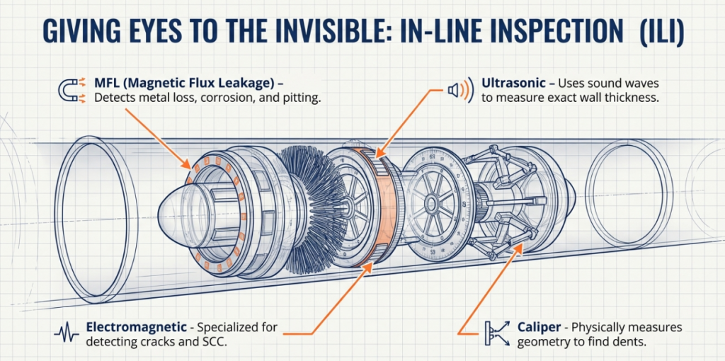
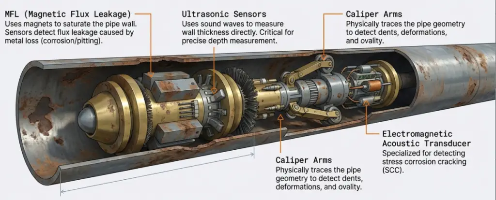
Modern pipeline operators have access to four primary ILI technologies, each designed to address specific threats:
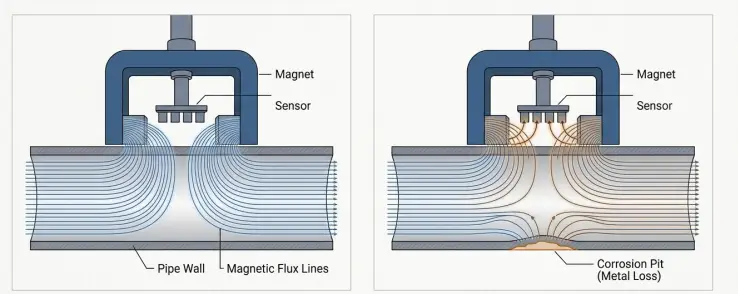
1. Conventional Magnetic Flux Leakage (MFL)
How It Works: Conventional MFL saturates the pipe wall with a powerful magnetic field. Metal loss (corrosion defects) disrupt this field, causing flux to “leak” outside the wall. A circumferential array of sensors detects this leakage signal, which is recorded as an analog log for later interpretation.
Capabilities:
- Most widely used device for corrosion detection
- Highly effective at detecting the presence of metal-loss defects
- Baseline tool for broad, initial screening
Limitations:
- No Precise Sizing: Cannot determine length or width of anomalies
- Subjective Grading: Output relies on analog signal amplitude, classified as Light (<30% penetration), Moderate (30-50%), or Severe (>50%)
- Location Ambiguity: Cannot distinguish between internal and external defects
- Requires Correlation Excavations: Costly “digs” are necessary to verify signal amplitudes against actual defect depth
- Blind to Uniform Loss: Cannot detect uniform wall thickness reduction, only profile changes
Best For: Cost-effective screening of low-risk pipelines and initial threat detection.
2. High-Resolution Magnetic Flux Leakage (MFL)
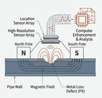
The Evolution: High-Resolution MFL employs the same magnetic principle as conventional tools but incorporates significant technological upgrades:
- Higher Sensor Density: Many more smaller, more sensitive sensors create a detailed “picture” of the pipe wall
- Location Sensors: A secondary bank of tri-axial sensors determines whether anomalies are internal or external
- Digital Processing: Raw data is converted into a high-fidelity digital profile, enabling computer enhancement and precise measurement
Capabilities:
- Accurate Sizing: Provides precise dimensions of defects (depth, length, and width)
- Clear Location: Reliably distinguishes between internal and external defects
- Digital Output: Results delivered as digital wall thickness profiles, not analog logs
- Direct Assessment: Data is precise enough for defect assessment without correlation excavations, enabling failure pressure calculations
The Trade-off: The cost of a high-resolution survey is approximately 5–6 times that of a conventional MFL survey. However, this premium is often offset by eliminating costly excavations and enabling more confident asset management decisions.
Best For: Detailed integrity assessments, pitting corrosion analysis, interacting defects, and failure pressure calculations.
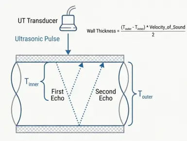
3. Ultrasonic Tools (UT)
How It Works: An ultrasonic transducer emits a high-frequency sound pulse toward the pipe wall. The tool measures the time for this pulse to reflect off both the inner and outer walls. The time difference directly calculates exact wall thickness. The “standoff” measurement (time to first reflection) indicates whether metal loss is internal or external.
Capabilities:
- Direct Measurement: Provides actual wall thickness, not an inference based on a signal
- High Sensitivity: Can detect wall thinning of as little as 10%
- Definitive Location: The standoff measurement naturally identifies corrosion as either internal or external
- Unmatched Accuracy: Among the most precise ILI technologies available
Critical Limitations:
- Requires Liquid Couplant: Must operate in a homogenous liquid environment to transmit sound waves. For gas lines, this requires a special liquid or gel slug, adding operational complexity
- Slow Speed: Must operate at relatively slow speeds (~1 m/s maximum) to ensure all data is collected
Best For: Baseline integrity checks, pre-inspection clearance runs, and applications where absolute wall thickness verification is critical (typically liquid lines).
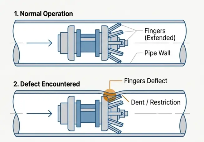
4. Geometry and Caliper Tools
How It Works: The tool is fitted with a series of high-sensitivity “fingers” around its circumference. As it moves, these fingers press against the inner pipe wall. When a dent or restriction is encountered, the fingers deflect (compress). The amplitude of deflection is recorded to size the anomaly, while an odometer wheel tracks distance for location.
Capabilities:
- Simple, Reliable Detection: Cost-effective detection of diameter restrictions and deformations
- Low Operational Cost: Relatively inexpensive compared to other ILI methods
Significant Limitations:
- Limited Circumferential Resolution: The finite number of sensor arms means true dent shape can be misinterpreted
- Mechanical Artifacts: Fingers can “lift off” at girth welds or sharp edges, distorting perceived depth and shape
- Requires Interpolation: Sparse data must be interpolated to approximate true dent profile
- No Metal Loss Detection: Cannot detect or size corrosion defects
Best For: Cost-effective detection of geometric deformations in low-risk pipelines.
The Data Revolution: High-Resolution Inspection Transforms Diagnosis
The difference between low-resolution and high-resolution data is profound:
- Low-Resolution Data (mechanical caliper): Produces fragmented, sparse data requiring significant post-processing. Often leads to unnecessary digs based on simple depth rules or, worse, misinterpretation of severe threats.
- High-Resolution Data (ultrasonic geometry): Provides true-to-life profiles, enabling precise shape characterization and accurate engineering assessment.
Multi-Mission Integration: One Run Replaces Three
Historically, assessing different threats required different tools and multiple runs:
- One for metal loss (MFL)
- One for geometry (caliper)
- One for positioning (IMU)
The Modern Solution: Advanced multi-mission systems now integrate MFL, high-density geometry sensors, and Inertial Measurement Unit (IMU) mapping into a single run.
Advantages:
- Reduced Downtime: One run instead of three
- Enhanced Data Correlation: All datasets are perfectly aligned by default
- Improved First-Run Success: ~95% success rate (vs. industry benchmark of ~90%)
The Hidden Threat: Geohazards and Pipeline Movement
Beyond corrosion and mechanical damage, the most insidious threats are often those caused by ground movement and environmental instability.
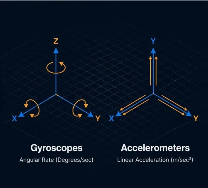
Understanding Inertial Measurement Units (IMU)
An IMU is the core technology for accurately mapping a pipeline’s absolute position in three-dimensional space, using:
- Gyroscopes: Measure angular rate (degrees per second) around three axes (X, Y, Z), determining the tool’s orientation and direction changes
- Accelerometers: Measure linear acceleration along the same three axes, tracking movement through space
Combined with odometer data and corrected by periodic above-ground GPS control points, IMU data generates a continuous, highly accurate 3D centerline map of the pipeline.
From Centerline Coordinates to Actionable Bending Strain
The true power of IMU mapping emerges when comparing data from successive runs. By quantifying movement and its effect on the pipeline:
Calculating Curvature: The change in pipeline angle over distance defines curvature (κ). A change in curvature between runs indicates movement.
Calculating Bending Strain: Bending strain (ε) is directly proportional to pipeline diameter (D) and curvature:
ε = (Pipe Diameter / 2) × Curvature (κ)
This allows direct assessment of stress induced by ground movement, pinpointing high-strain areas where risk is greatest.
Case Study: Detecting a Landslide Before Failure
An inertial survey of an NPS 30 gas line in a mountainous region with known slope instability revealed:
- Finding: 1.7 meters of horizontal movement over a 500-meter section
- Impact: Large bending strains at slide boundaries, increasing risk at multiple girth welds
- Action: Geotechnical survey confirmed findings; the section was excavated to relieve strain and prevent failure
This demonstrates the critical value of ILI in detecting unknown areas of slope instability before they become catastrophic.
Part III: Assessment and Diagnosis
From Signal to Diagnosis: Quantifying Defect Severity
Once an anomaly is detected, the next critical step is assessment: Is the pipeline safe to operate at its Maximum Allowable Operating Pressure (MAOP)?
This assessment is governed by established engineering codes based on decades of research, full-scale burst tests, and fracture mechanics principles.
The Assessment Spectrum: Three Approaches
1. ASME B31G (Original Criterion)
Approach:
- Defect Model: Simplistic parabolic shape (Area = 2/3 × L × d)
- Flow Stress: 1.1 × SMYS (Specified Minimum Yield Strength)
- Result: Highly conservative; often flags safe pipelines for repair, especially for long, shallow defects
Use Case: Foundational screening tool for initial assessments.
2. Modified B31G / RSTRENG (Industry Standard)
Approach:
- Defect Model: More realistic rectangular area (Area = 0.85 × L × d)
- Flow Stress: SMYS + 10,000 psi (better reflects true material properties)
- Result: More accurate than original B31G, reducing unnecessary repairs while maintaining safety
Key Advantage: Permits corroded areas ≤20% wall thickness to remain in service under specific conditions, regardless of length.
Use Case: Industry-standard detailed and accurate fitness-for-service assessments.
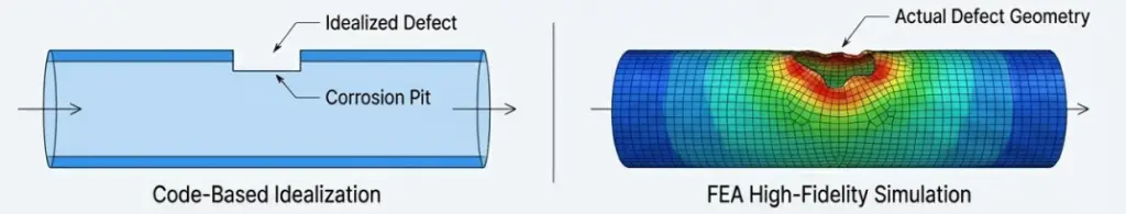
3. Finite Element Analysis (FEA)
Approach:
- Creates a 3D CAD model of the pipe and defect
- Divides the model into thousands of finite elements
- Uses advanced solvers to simulate pressure loads and calculate stress/strain in each element
- Models actual defect geometry and material stress-strain curve
Advantages Over Codes:
- Models actual defect geometry instead of idealized shape
- Uses true material stress-strain curve, accounting for plasticity and strain hardening
- Accurately simulates complex stress states (wrinkles, dents, elbows)
- Provides highest precision assessment
Use Case: Critical defects, complex geometries, interacting threats, and high-consequence areas.
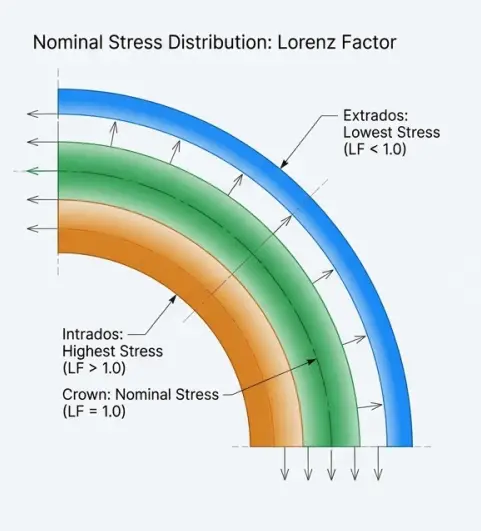
Special Consideration: Elbows and Complex Geometry
Stress in a pipeline is not uniform. In elbows, pressure creates significantly higher stress on the inner curve (intrados) and lower stress on the outer curve (extrados), described by the Lorenz Factor (LF):
- Intrados: LF = 1.25 (25% higher stress)
- Crown: LF = 1.0 (nominal stress)
- Extrados: LF = 0.875 (12.5% lower stress)
Critical Implication: An identical corrosion pit is far more severe on the intrados. Standard codes often fail to capture this complexity; FEA provides precise evaluation.
Part IV: Repair and Mitigation
Three Principal Repair Methods
Once a defect is deemed unacceptable, a repair must restore pipeline integrity. The method depends on defect type, severity, and operational constraints.
1. Coating Repair
- For: Minor corrosion where structural integrity is not compromised
- Function: Arrests corrosion growth by restoring the protective barrier
- Advantage: Minimally invasive
2. Cut-Out and Replacement
- For: Severe or through-wall defects requiring complete removal
- Process: Remove the damaged pipe section entirely and weld in a new piece
- Characteristic: Most definitive but most disruptive method
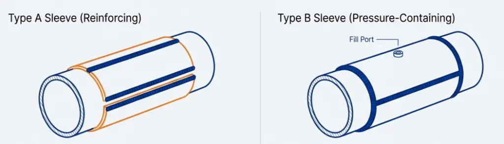
3. Welded Steel Sleeves
Welded sleeves are classified into two categories:
Type A Sleeve (Reinforcing)
- Function: Reinforces the pipe against localized external loads and arrests crack growth (not pressure-containing)
- Application: Non-leaking defects like external corrosion, gouges, dents
- Installation: Welded only along longitudinal seams (simpler, faster)
Type B Sleeve (Pressure-Containing)
- Function: Creates a fully sealed enclosure around the defect, making it pressure-containing
- Application: Through-wall defects, active leaks, severe corrosion where breach is possible
- Installation: Fully welded around entire perimeter, often with epoxy filler to transfer load
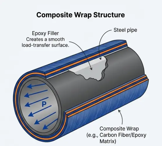
4. Composite Repair Wraps (Modern Alternative)
Advantages:
- No Hot Work: Eliminates risk of explosion on live pipelines
- Conformability: Can be applied to complex geometries (elbows, tees)
- Corrosion Immune: The composite material itself is immune to corrosion
- Standards: Governed by ASME PCC-2 and ISO 24817
- Capability: Can repair defects up to 80% wall loss
Integrated Analysis: Correlating Multiple Threats
The true value of multi-mission tools lies in analyzing a single, homogenous dataset where all features are perfectly aligned. This enables identification of interacting threats that pose significantly higher risk:
Examples of Threat Interaction:
Dent on a Girth Weld
- Amplifies structural significance due to potential material and construction anomalies
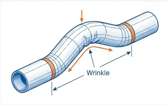
Wrinkle from Compressive Strain
- Direct result of compressive forces quantifiable by IMU strain analysis
Corrosion in a High-Strain Area
- More likely to fail than identical corrosion in stable sections
Case Study: Upheaval Buckle Assessment
An inspection of an NPS 8 gas line that buckled due to elevated temperatures with insufficient backfill demonstrated the power of combined data:
- Geometry Data (Caliper): Precisely identified a 1 cm wrinkle on the bottom of the pipe
- Mapping Data (IMU): Calculated high bending strain of 1.1% at the buckle’s apex
- Integrated Insight: Confirmed failure mechanism (compressive buckling) and provided inputs for full fitness-for-service assessment
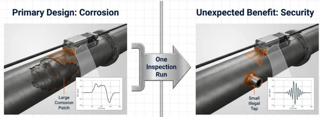
Beyond Corrosion: Security and Pilferage Detection
A modern advantage of high-resolution MFL is an unexpected benefit: detection of unauthorized pipeline connections.
The Problem
Product theft via unauthorized connections is a major, growing global threat to pipeline operators. Beyond revenue loss, these connections compromise pipeline integrity and create environmental and safety hazards.
The Solution
Modern high-resolution MFL systems can identify the unique signature of theft, specifically detecting pinholes down to 2 mm in diameter.
Capabilities:
- Detects coincidence of new fixtures and small-diameter metal loss
- Formally validated through blind tests and in-field dig verification
- Enables operators to scan, identify, verify (through excavation), and secure against theft
The Complete Integrity Lifecycle
Modern pipeline integrity is a continuous cycle:
INSPECT → ASSESS → STRATEGIZE → REPAIR
   ↓
(Data feeds back into system to build predictive models)
INSPECT
Detect the initial signal with high-resolution ILI tools.
ASSESS
Diagnose severity using established codes (ASME B31G, Modified Criterion) and advanced methods (FEA) where justified.
STRATEGIZE
Manage long-term integrity with predictive maintenance frameworks like ASME B31.8S.
REPAIR
Implement durable solutions from welded sleeves to composite wraps, based on defect type and severity.
The Strategic Outcome: Safe, Compliant, Profitable Assets
Adopting a predictive integrity framework transforms pipeline management from a cost center into a strategic advantage:
Enhanced Safety
- Quantifiable reduction in failure risk
- Protection of public and environment
Regulatory Confidence
- Defensible, data-backed Integrity program
- Demonstrated compliance with all standards (ASME, API, PHMSA, PSR)
Extended Asset Life
- Proactive interventions arrest degradation
- Defers costly capital replacement projects
Optimized Operations
- Maintenance budgets spent on prevention, not reaction
- Maximizes value of every operational dollar
Conclusion: From Uncertainty to Intelligence
Modern pipeline integrity management is a paradigm shift from reactive “run to failure” maintenance to data-driven, predictive asset stewardship. By leveraging advanced ILI technologies, rigorous engineering assessment, and strategic repair methodologies, operators transform the uncertainty of hidden threats into actionable intelligence.
The result: Pipelines that operate safely, reliably, and profitably for decades.
The journey: From Signal to Solution.
Key Takeaways
- Multi-threat detection now possible in single ILI run via integrated systems
- High-resolution MFL provides accurate sizing, eliminating costly correlation digs
- IMU mapping detects geohazards and quantifies bending strain from ground movement
- Graduated assessment approach (B31G → Modified → FEA) matches rigor to consequence
- Modern repair methods from welded sleeves to composites offer flexibility and reliability
- Data integration enables identification of interacting threats for prioritized mitigation
- Security applications of high-res MFL detect unauthorized connections and pilferage
- Predictive frameworks extend asset life, optimize budgets, and ensure compliance