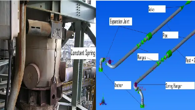
In all critical process and power plant units’ the use of spring hangers are quite common. These are mostly used near equipment to bring nozzle loads within vendor-allowable values. Purchasing a spring hanger must serve the appropriate function of carrying the loads within its working range without failure. To maintain the quality of spring hangers the hangers must meet several technical and general requirements. This article will mention about few such important points. For more information about spring hangers click here to visit my earlier articles on spring hangers.
The following requirements at a minimum must be met by the vendor while delivering the spring hanger supports:
- Spring support mechanical design, material & fabrication shall be performed by the vendor according to MSS SP 58 unless specified otherwise in this specification.
- Spring support shall meet the requirements of the MSS SP 69, “Pipe Hanger and Supports- Selection and Application” unless specified otherwise in this specification.
- Spring support shall meet the requirements of the MSS SP 89, “Pipe Hanger and Supports – Fabrication and Installation Practices” unless specified otherwise in this specification.
- Spring support shall be supplied in line with the requirements specified in Datasheet.
- Spring support assembly shall be designed to withstand 10000 plus load reversals at maintained consistency.
- All parts of the spring support assembly shall be designed to withstand 2 times the operating load or hydro test load, whichever is higher.
- All alloy steel springs shall be shot-peened as per supplementary requirement S3 of ASTM A125.
- All Hot wound alloy steel springs shall be examined by the magnetic particle as per supplementary requirement S2 of ASTM A125.
- Spring shall have a surface protection coating suitable for saline coastal conditions e.g. plastic coating.
- Each spring support shall be factory pre-set and locked to the cold load given in Datasheet.
- All spring supports shall be provided with a locking device (bolt & nut type) which must be designed to re-lock the spring support at any load position within the range of the model.
- All spring support shall be provided with means of positively and firmly locking the piston plate for hydrostatic testing of the pipe.
- All “can type” spring supports shall have a Teflon pad on the top slide plate of the spring for temperatures up to 200°C. The thickness of pads shall be a minimum of 10 mm for Teflon and 12.5 mm for graphite. It shall be firmly secured by welding 50mm wide X 8 mm (10 mm in the case of Graphite) stopper plates to the load flange. The additional Teflon pad shall be glued with adhesive.
- All springs shall be effectively enclosed in a robust casing constructed of steel which is to be provided with a 50 X 50 mm opening at the lowest point in the casing to drain any rainwater or other garbage/ liquid which may enter.
- For lifting large-size spring support (with a dead weight of more than 50 Kg), lifting lugs shall be provided.
- All springs shall have an affixed load and travel plate on which hot and cold positions are clearly marked. The positioning plate shall have an integral pointer to indicate the load on the spring at any time. The load may be indicated by punching also.
- The manufacturer shall submit a spring support assembly drawing with a hot load, cold load, spring constant, and all the dimensions in detail indicating the overall length.
- All spring support shall be delivered as a complete assembly, complete with a blocking device installed.
- The Vendor shall comply with the inspection & testing requirements of MSS SP 58.
- The Purchaser and Company reserve the right to carry out quality and technical review at both Supplier’s and Sub-Supplier’s works including review of quality documentation.
- Test reports for all mandatory (as well as supplementary, wherever specified) tests shall be furnished.
- The supplier shall provide a warranty for the material for eighteen (18) months from the date of delivery or twelve months from the date of commissioning whichever is longer.

Materials
The material of springs shall meet the minimum requirements as mentioned in ASTM A125. The material of construction shall be as follows.
- Spring ASTM A689 (A 322 Gr. 6150 I Gr. 9260)
- Turnbuckle A105 I A36
- Plates/Flats A36
- Rounds A36
- Name Plate Aluminium
- Stud Bolts/Nuts A193 B7 I A194 2H
- Indicator Aluminium
- Welding Electrodes 1
Painting and Coating
Spring housing shall be painted in accordance with approved specifications or standards. All threaded components shall be hot dip galvanized as per ASTM A123.
The following additional information shall be legibly and conspicuously attached to the spring casing:
- Project Name
- Spring Support Tag
- Vendor’s Model No.
- Load Scale (N)
- Travel Scale (mm)
- Hot Load Position (Red indicator)
- Cold Load Position (Green indicator)
- Spring Rate
Documents to be submitted with tender:
- Sketches/catalogs indicating selection criteria for the spring model.
- List of materials for spring, housing, and their painting/coating detail.
