
Pre-requisites for commissioning and start-up of a Process Pump:
Before commissioning and starting up of any equipment some preparation must be done. There will be some mandatory requirements, that should be fulfilled. So Process Pump is not an exception. At the same time process pumps, being vibration prone and sensitive, the utmost care has to be exercised. So before starting up the pump set, make sure that the following requirements are met:
- The pump set has been properly connected to the electric power supply and is equipped with all protective devices.
- The pump has been primed with the fluid to be handled.
- The direction of rotation has been checked. (The correct direction of rotation of motor and pump is in the clockwise direction (seen from the motor end))
- All auxiliary connections required are connected and operational.
- The lubricants have been checked.
Filling in the lubricant in bearing bracket of Process Pump:
Fill the bearing bracket of the Process Pump with lubricating oil. The constant-level oiler is screwed into the upper tapping hole of the bearing bracket. If no constant-level oiler is provided on the bearing bracket, the oil level can be read in the middle of the oil level sight glass arranged at the side of the bearing bracket. Note that Insufficient lubricating oil in the reservoir of the constant-level oiler damages the bearings. So
- Regularly check the oil level.
- Always fill the oil reservoir completely.
- Keep the oil reservoir properly filled at all times.
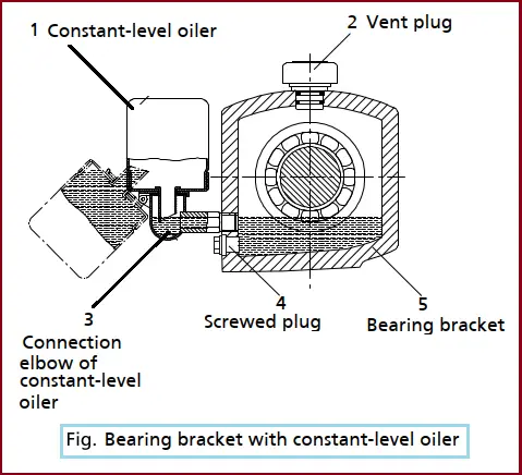
- Remove the protective cage.
- Unscrew the vent plug (2).
- Hinge down the reservoir of the constant-level oiler (1) from the bearing bracket (5) and hold it in this position.
- Pour in the oil through the vent plug tapping hole until oil appears in the connection elbow of the constant-level oiler (3).
- Fill the reservoir of the constant-level oiler (1) with oil up to the maximum level.
- Snap the reservoir of the constant-level oiler (1) back into the operating position.
- Screw the vent plug (2) back in.
- Fit the protective cage.
- After approximately 5 minutes, check the oil level in the reservoir of the constant-level oiler (1). It is important to keep the reservoir properly filled at all times, to ensure an optimum oil supply. Repeat steps 1 – 8, if necessary.
- To verify the correct function of the constant-level oiler (1), slowly drain the oil through the drain plug (4) until air bubbles can be seen in the oiler.
Note that, An excessively high oil level can lead to a temperature rise and to leakage of the fluid handled or oil.
Shaft seal
- Shaft seals are fitted prior to delivery.
- Observe the instructions on dismantling or reassembly on the operator’s manual.
- If applicable, fill the reservoir of non-pressurized external fluid in accordance with the general arrangement drawing.
- Prior to starting up the pump, apply barrier pressure as specified in the general arrangement drawing.
- Apply the quantities and pressures specified in the datasheet and the general arrangement drawing.
Filling and venting the Process Pump:
Before starting up the pump set, vent the pump and suction line and fill both with the fluid to be handled.
- Vent the pump and suction line and fill both with the fluid to be handled.
- Fully open the shut-off element in the suction line.
- Fully open all auxiliary connections (barrier fluid, flushing liquid, etc).
Final check before Starting the Process Pump:
- Remove the coupling guard and step guard, if any.
- Check the coupling alignment; re-align the coupling, if required.
- Check that the coupling and shaft can easily be rotated by hand.
- Re-install the coupling guard and step guard, if any.
- Check the distance between coupling and coupling guard. The coupling guard must not touch the coupling.
Water cooling:
Observe the cooling water quality. Also, observe the following quality data of the cooling water:
- Not deposit forming
- Not aggressive
- Free from suspended solids
- Hardness on average 5 °dH (~1mmol/l)
- pH > 8
- Conditioned and neutral with regard to mechanical corrosion
- Inlet temperature tE= 10 to 30 °C Outlet temperature tA= maximum 45 °C
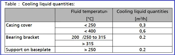
Cooling of the pump:
The casing cover, the bearing bracket and the casing support on the baseplate can be cooled. Observe the following quality data of the cooling water:
- Maximum permissible cooling liquid pressure: 10 bar
- Maximum permissible cooling liquid test pressure: 15 bar
- Observe the specified cooling liquid quantity.
Cooling of the shaft seal:
- Cool the shaft seal.
- Provide sufficient quantities of cooling liquid (see table).
Heating up/keeping warm the pump (set):
Prior to pump start-up, heat up the pump as described in the operating manual. Observe the following when heating up the pump (set) and keeping it warm:
- Make sure the temperature is increased continuously.
- Max. heating speed: 10 °C/min (10 K/min)
If the pump is used for handling fluids with fluid temperatures exceeding 150 °C, make sure that the pump has been heated throughout before starting it up. The temperature difference between the pump’s surface and the fluid handled must not exceed 100 °C (100 K) when the pump is started up.
Start-up:
- Fully open the shut-off valve in the suction head/suction lift line.
- Close or slightly open the shut-off valve in the discharge line.
- Switch on the motor.
- Immediately after the pump has reached full rotational speed, slowly open the shut-off valve in the discharge line and adjust it to comply with the duty point.
- When the operating temperature has been reached and/or in the event of leakage, switch off the pump set and let it cool down. Then retighten the bolts between lantern and casing.
- Check the coupling alignment and re-align the coupling if required.
Check that
- The piping system connected to the pump set has been cleaned.
- Pump, suction line and inlet tank, if any, have been vented and filled with the fluid to be pumped.
- The filling and venting lines have been closed.
- Never operate the pump with the shut-off elements in the suction line and/or discharge line closed.
- Only start up the pump set with the discharge side gate valve slightly or fully open.
- Never operate the pump set without liquid fill.
- Prime the pump as specified. (⇨ Section 6.1.4 Page 31)
- Always operate the pump within the permissible operating range.
In case of Abnormal noises, vibrations, temperatures or leakage
- Switch off the pump (set) immediately.
- Eliminate the causes before returning the pump set to service.
Checking the shaft seal
The mechanical seal only leaks slightly or invisibly (as vapor) during operation. Mechanical seals are maintenance-free.
Operating limits
- Comply with the operating data indicated in the datasheet.
- Avoid prolonged operation against a closed shut-off valve.
- Never operate the pump at temperatures exceeding those specified in the datasheet or on the nameplate unless the written consent of the manufacturer has been obtained.
Ambient temperature
Observe the specified limits for permissible ambient temperatures.
- Permissible ambient temperature: Maximum 43 °C: Minimum See datasheet
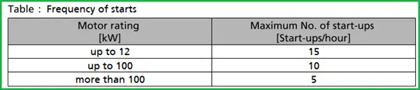
Frequency of starts
The frequency of starts is usually determined by the maximum temperature increase of the motor. This largely depends on the power reserves of the motor in steady-state operation and on the starting conditions (d.o.l., star-delta, moments of inertia, etc). If the start-ups are evenly spaced over the period indicated, the following limits can be used for orientation for a start-up with the discharge-side gate valve slightly open:
Do not re-start the pump set before the pump rotor has come to a standstill.
The density of the fluid handled
The power input of the pump increases in proportion to the density of the fluid handled. Hence always observe the information on fluid density indicated in the datasheet and make sure the power reserve of the motor is sufficient.
Abrasive fluids
Do not exceed the maximum permissible solids content specified in the datasheet. When the pump handles fluids containing abrasive substances, increased wear of the hydraulic system and the shaft seal are to be expected. In this case, reduce the intervals commonly recommended for servicing and maintenance.
Pump Commissioning Checklist
The commissioning of Process Pumping systems is a complex process that requires a structured approach. A pump commissioning checklist validates the operation of pumps through correct installation, proper lubrication, and simulation of instrumentation and protection devices. The following checklist highlights some of the areas that need to be verified when commissioning pumping systems:
- Pumps in place and properly grouted, anchoring installed as per specification
- Pump tag and nameplate permanently affixed
- Pump environment clean with adequate access for maintenance
- Distribution piping complete, including pipe fittings and accessories, bleed and makeup water lines and safety reliefs; piping type and flow direction labeled on piping, valves properly tagged
- System flushing complete and strainers cleaned
- Required valves and balancing valves installed and balancing completed; TAB report reviewed for pump flows, pressure or head, electrical data
- Temperature, pressure, and flow gauges and sensors installed per specification; test ports installed near all control sensors
- Flow switch and flow meters installed as required and per specification
- Expansion tanks verified to not be air-bound and system completely full of water
- Air vents and bleeds at high points of systems functional
- Vibration isolation devices installed and functional
- Factory alignment/field alignment correct
- No visible leaks
- Pump lubricated
- Automatic valves stroke fully and close tightly
- Pump electrical supply disconnects in place and labeled; all electrical connections tight
- Motor safeties in place and operable
- All control devices, tubing, and wiring complete; control system interlocks hooked up and functional
- Water treatment system or plan installed
- VFD commissioned in accordance with the manufacturer’s instructions.
- Specific commissioning actions will depend on the type and extent of the system to be commissioned.
References:
Send me.
I am extremely impressed with your writing skills as smartly as with the format in your blog. Is this a paid theme or did you modify it your self? Anyway stay up the nice quality writing, it’s uncommon to peer a great blog like this one nowadays.
Today i have download ur valuable notes & gone through it.Also share it in more then 10 people & found realky informative .
Amaging cong to u & thanks lot .