
Appendix V of ASME B31.3 code covers the application of the Linear Life Fraction Rule, which provides a method for evaluating variations at elevated temperatures above design conditions where material creep properties control the allowable stress at the temperature of the variation.
What is Creep-Rupture Usage Factor?
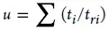
The calculated value of Creep-Rupture Usage Factor “u” indicates the nominal amount of creep-rupture life expended during the service life of
the piping system. If u ≤ 1.0, the usage factor is acceptable. If u > 1.0, the designer shall either increase the design conditions (selecting a piping system components of a higher allowable working pressure if necessary) or reduce the number and/or severity of excursions until the usage factor is acceptable
i – as a subscript, 1 for the prevalent operating condition
ti – total duration, h, associated with any service condition, i, at pressure, Pi, and temperature, Ti
tri – allowable rupture life, h, associated with a given service condition i and stress, Si
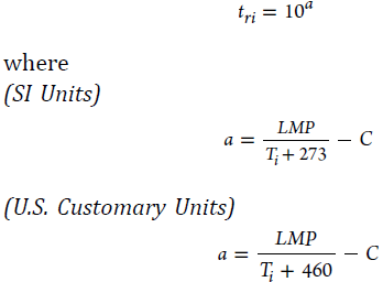
Ti – temperature, °C (°F), of the component for the coincident operating pressure-temperature condition i under consideration
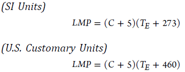
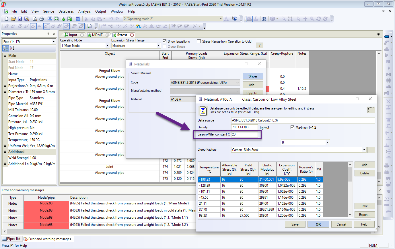
C – Larson-Miller constant. C = 30 for 9Cr–1Mo–V; C = 20 for carbon, low, and intermediate alloy steels, except 9Cr–1Mo–V; C = 15 for austenitic stainless steel and high nickel alloys
TE – effective temperature, °C (°F) from Table A-1 or Table A-1M, find the temperature corresponding to basic allowable stress equal to the equivalent stress, Si, using linear interpolation if necessary. This temperature, TE, is the effective temperature for service conditions i.
The equivalent stress, Si, is calculated as follows
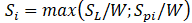
SL – the maximum stress due to sustained loads, during service conditions i
Spi – pressure-based equivalent stress, MPa (ksi)
Pmax – maximum allowable gage pressure, kPa (psig), for continuous operation of pipe or component at design temperature, considering allowances, c, and mill tolerance, but without considering weld joint strength reduction factor, W; weld joint quality factors, Ej; or casting quality factor, Ec
Sd – allowable stress, MPa (ksi), at design temperature, °C (°F)
Pi – gage pressure, kPa (psig), during service condition i
Calculation of Creep-Rupture Usage Factor
The latest version of modern professional PASS/START-PROF software includes the ability to automatically calculate the Creep-Rupture Usage Factor for the piping system.
Firstly, the material database contains the Larson-Miller constant for every material as shown in Fig. 1 below.
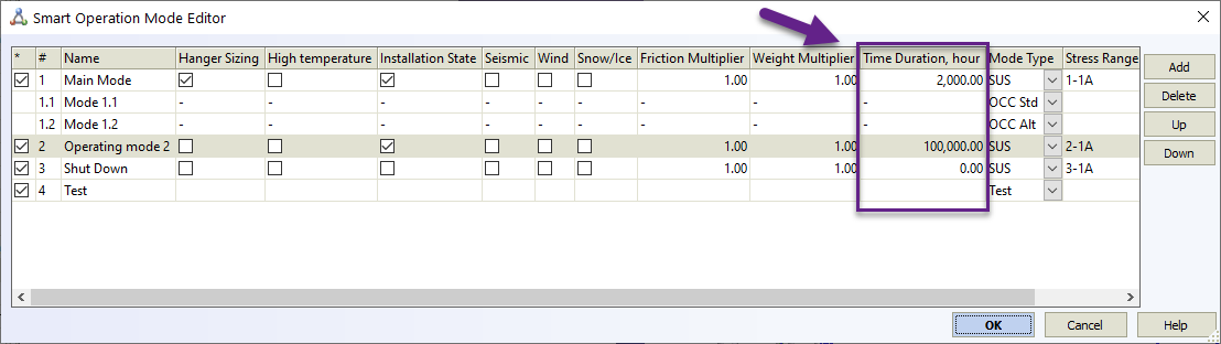
Secondly, the operation mode editor contains the time duration for each operation mode
And thirdly, the code stress table contains the column, where the “u” factor is printed. If you move the mouse over the table cell, you will see the calculation details (As shown in Fig. 3 below)

The more information about the new modern pipe stress analysis software PASS/START-PROF and analysis methods you may learn from the resources web page and from Start-Prof basics and tutorials.