
External loads on static equipment nozzle flange joints must be assessed in order to comply with code requirements. In general, except for the flanged joints at high temperatures, the external forces and bending moments have little effect on the joint integrity of a properly assembled joint as long as the loads are within allowable design stress levels. It is a standard engineering practice to limit the external loads on flanged joints. So, selecting an appropriate method for assessing the effect of piping bending moments and external loads during the design phase becomes a task in trying to set a limit that encourages good piping design. There are various methods available for assessing the effects of external loads on nozzle flanges. In this article, we will discuss some of those methods. The points that will be covered in this article are:
- ASME Interpretation BPV VIII-1-16-85
- ANSI Flange Pressure Reduction Options In PV Elite
- Code Case 2901
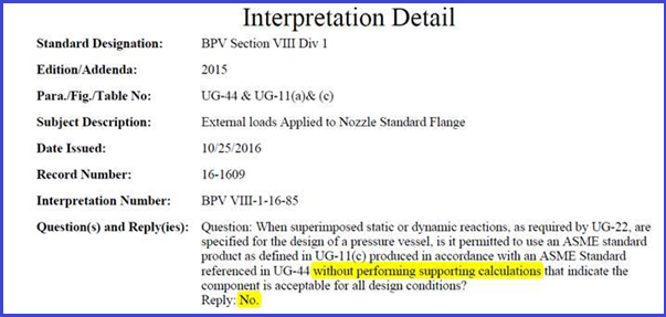
What Code Interpretation BPV VIII-1-16-85 States
This interpretation states that if you have external loadings acting on a nozzle you have to consider them on the flange too.
In 2013, however, PVP2013-97814 was written to address this issue. But many users complained that their jurisdictions did not/would not accept such a published (peer-reviewed) paper by a reputable author, because it did not have the approval of the ASME Boiler and Pressure Vessel Code Committee.
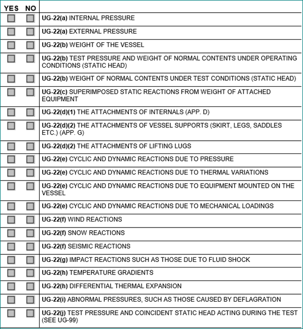
Compliance With ASME VIII-1, Paragraph UG-22:
Internal and external design pressures are not the only criteria used when designing pressure vessels. ASME VIII-1, paragraph UG-22, requires that all external loads acting on the pressure vessel be taken into account as well.
These include forces and moments that arise from attached piping and equipment, the weight of the vessel and its contents, liquid static head as well as wind and seismic induced reactions.
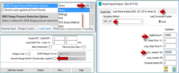
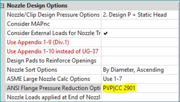
ANSI Flange Pressure Reduction Options:
- Select a method for ANSI flange pressure reduction. Several methods are available to de-rate the flange MAWP based on external loads. If flanges are externally loaded they have the potential to leak. To keep this from occurring, it might be necessary to choose a heavier class of flange than one that is good for the design pressure per the B16.5/47 standard.
- At the time of this writing (November 2017), the ASME Code has no rules on a particular method to use. They do however state (in a Code Case) that the external loadings must be considered.
Methods Available in PV Elite:
- Kellogg Method
- PVP Method
- 50% Stress Method
- DNV Method
Assessing the flange MAWP reduction method in PV Elite:
Kellogg Method –
The Kellogg method is well-known and conservative. The axial load and moment are used to compute an equivalent pressure that is then deducted from the flange rating from the B16/47 table.
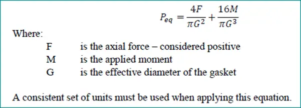
PVP Method –
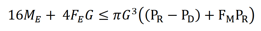
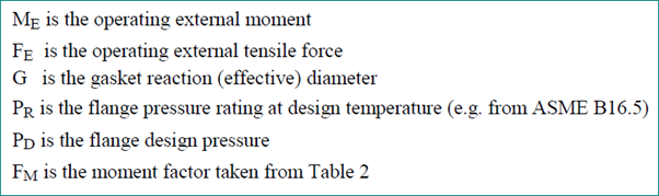
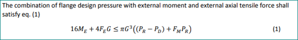
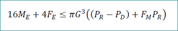
This method is taken from the paper: ‘Improved Analysis of External Loads on Flanged Joints’ PVP2013-97814 by Dr. Warren Brown delivered in Paris July 14-18 2013 published by ASME. MAWP of the flange is adjusted so that the following equation is observed:
Sustained forces and moments must be entered for those results to be meaningful. Otherwise, the computed flange rating is zero.
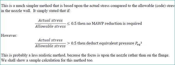
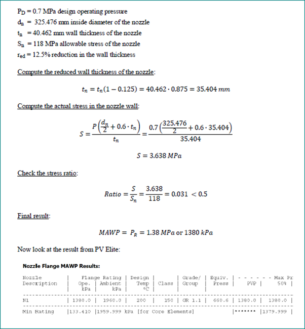
50% Stress Method –
If the computed stress/allowable stress is < 0.5 on the pipe wall, then the allowable pressure is the full rating from the ANSI/ASME standard. If the stress ratio is >= 0.5, then the full equivalent pressure based on the Kellogg method is subtracted from the flange rating. This method looks at the stress in the nozzle wall to determine the MAWP. These are the data:
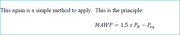
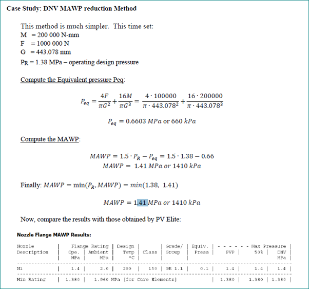
DNV Method –
The DNV method is considered to be a bit unconservative. It is essentially 1.3 times the flange rating minus the equivalent pressure based on the Kellogg method. The idea is that because the flanges will be a hydro test at elevated pressure and because there will loading applied (flanges in the piping system), then their rating can be elevated using the above equation. Most piping is tested to 1.5 times the design pressure, but we use a factor of 1.3 for conservatism because 1.3 is the factor used in Division 1 for hydro testing pressure vessels.
Note- The equivalent pressure is the pressure derived from the Kellogg Equation.
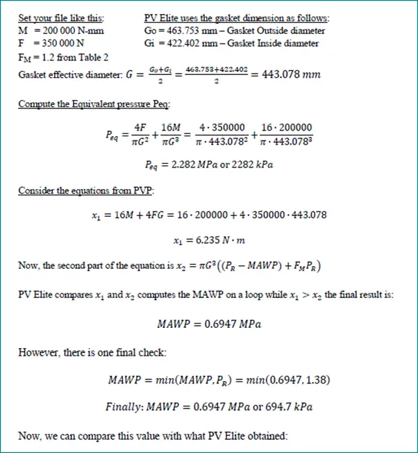
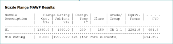
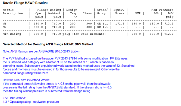
Analysis result-
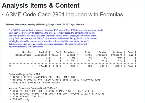
ASME BPVC Code Case 2901:
Does Code Case 2901 available in PV Elite?
Yes, the PVP method in PV Elite is essentially the same thing as the Code Case.
ASME BPVC Code Case 2901-
The PVP MAWP Reduction Method-
What’s New in PV Elite 2019:
This presentation is prepared by Mr. Deepak Sethia who is working in ImageGrafix Software FZCO, the Hexagon CAS Global Network Partner in the Middle East and Egypt. He has extensive experience in using Caesar II and PV Elite software and troubleshooting.
Hi Anup sir,
Thank you for valueable information and above snap calc.method from Ray Dela force.
I have review a new version of PV 2020 version that has a new tools to select “User define FM value for ANSI flange”. I know that FM comes from UG44 table.
But, in what case we shall select this option?
Please share any opinion. Thanks
Is there a way to model an excentric reducer connected to a nozzle in pvelite? i.e. 24″ nipple attached to the vessel, after the nipple there is an excentric reducer 24″ to 20″ and then the nozzle flange. Thak you