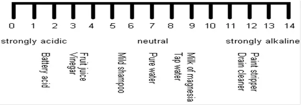
A pH Analyzer or pH meter is an electronic instrument that measures the pH value of a solution to measure acidity or alkalinity. pH can be measured and its value ranges between 0 and 14. Solutions with a pH<7 are acidic, whereas those with a pH>7 are alkaline. In “pH”, the term “p,” denotes the mathematical symbol for negative logarithm, and “H,” is the chemical symbol for Hydrogen. So, A pH meter or pH Analyzer analyzes the solution to measure the hydrogen ion activity in the solution.
A pH analyzer is an important instrument in many industrial and laboratory applications because it measures the acidity or basicity of a solution by determining the concentration of hydrogen ions (H+) in the solution. The pH value of a solution can range from 0 to 14, with 7 being neutral, values below 7 indicating acidity, and values above 7 indicating basicity.
Here are some reasons why pH analyzers are important:
- Quality control: In many industrial processes, the pH of a solution is a critical parameter that needs to be monitored to ensure product quality and consistency. For example, in the manufacturing of chemicals, pharmaceuticals, food, and beverages, the pH of a solution can affect the reaction rate, product yield, and sensory characteristics of the final product.
- Process optimization: By monitoring the pH of a solution in real time, pH analyzers can help operators adjust process variables such as temperature, pressure, and chemical dosing to optimize the process and improve efficiency.
- Environmental monitoring: In environmental monitoring applications, pH analyzers are used to measure the pH of water and wastewater to ensure compliance with environmental regulations and to monitor the health of aquatic ecosystems.
- Safety: In some industrial processes, the pH of a solution can affect the safety of workers and equipment. For example, acids and bases can be corrosive to metal pipes and vessels, leading to leaks and equipment failure. By monitoring the pH of a solution, pH analyzers can help operators take corrective action to prevent accidents and ensure the safety of personnel and equipment.
Overall, pH analyzers are important instruments in many industrial and laboratory applications because they provide accurate and reliable measurements of pH, which is a critical parameter in many chemical and biological processes.
What is pH?
The concentration of the hydrogen ion in a solution is a measure of its acidity or basicity. This concentration is expressed in terms of the pH of the solution. ie: the negative logarithm of the hydrogen ion concentration.
pH = -log[H+]
pH Measurement
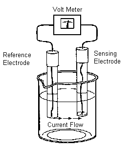
Electrochemical cell: The cell consists of a sensing electrode whose potential is directly proportional to pH, a reference electrode whose potential is independent of pH and the liquid to be measured. The overall voltage of the cell depends on the pH of the sample.
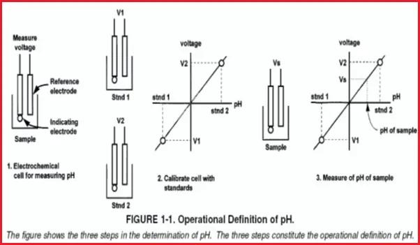
Because different sensing electrodes have slightly different responses to pH, the measuring system must be calibrated before use.
The critical step in the operational definition of pH is calibration.
pH analyzer working principle
The system is calibrated by placing the electrodes in solutions of known pH and measuring the voltage of the cell. Cell voltage is a linear function of pH, so only two calibration points are needed.
The final step in the operational definition is to place the electrodes in the sample, measure the voltage, and determine the pH from the calibration data.
pH Meter
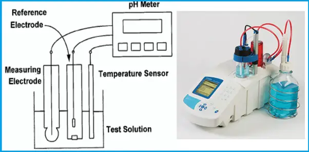
The cell consists of a measuring electrode, a reference electrode, a temperature-sensing element, and the liquid being measured. Refer to Fig. 4.
The voltage of the cell is directly proportional to the pH of the liquid.
The pH meter measures the voltage and uses a temperature-dependent factor to convert the voltage to pH.
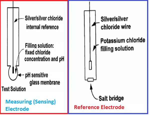
Measuring (Sensing) Electrode of pH Meter
- The outside surface of the glass membrane contacts the liquid being measured, and the inside surface contacts the filling solution.
- An electrical potential directly proportional to pH develops at each glass-liquid interface.
- Because the pH of the filling solution is fixed, the potential at the inside surface is constant.
- The overall potential of the measuring electrode equals the potential of the internal reference electrode plus the potentials at the glass membrane surfaces.
- Because the potentials inside the electrode are constant, the overall electrode potential depends solely on the pH of the test solution.
- The potential of the measuring electrode also depends on temperature. If the pH of the sample remains constant but the temperature changes, the electrode potential will change. Compensating for changes in glass electrode potential with temperature is an important part of the pH measurement.
Reference Electrode of pH Analyzer
- The reference electrode is a piece of silver wire plated with silver chloride in contact with a concentrated solution of potassium chloride held in a glass or plastic tube.
- The fixed concentration of chloride inside the electrode keeps the potential constant.
- A porous plug salt bridge at the bottom of the electrode permits electrical contact between the reference electrode and the test solution.
Temperature Compensation for pH Analyzers
- Millivolt signals produced by the pH and reference electrodes are temperature-dependent.
- However, the pH and reference electrode combination exhibits an iso-potential point, where the potential is constant with temperature changes.
- This iso-potential point is designed to be at 7.0 pH and 0 mV.
- Using the iso-potential point with theoretical knowledge of electrode behavior makes it possible to compensate (correct) the pH measurement at any temperature to a reference temperature (usually 25°C), using a temperature signal from the temperature element.
Converting Voltage to pH in pH meter
E(T) = E°(T) – 0.1984 T pH
E(T): Cell voltage at temperature T.
E°(T) is the sum of the following
- The potential of the reference electrode inside the glass electrode.
- The potential at the inside surface of the glass membrane.
- The potential of the external reference electrode.
- The liquid junction potential.
pH analyzer Liquid Junction Potential
- The junction separates a solution of potassium chloride on the left from a solution of hydrochloric acid on the right. The solutions have equal molar concentrations.
- Driven by concentration differences, hydrogen ions, and potassium ions diffuse in the directions shown. The length of each arrow indicates relative rates.
- Because hydrogen ions move faster than potassium ions, the positive charge builds up on the left side of the section and the negative charge builds up on the right side.
- The ever-increasing positive charge repels hydrogen and potassium ions. The ever-increasing negative charge attracts the ions.
- Therefore, the migration rate of hydrogen decreases, and the migration rate of potassium increases. Eventually, the rates become equal.
- Because the chloride concentrations are the same, chloride does not influence the charge separation or the liquid junction potential.

Buffers & Calibration
Fig. 7 shows the performance of an ideal cell: One in which the voltage is zero when the pH is 7, and the slope is -0.1984T over the entire pH range. In a real cell, the voltage at pH 7 is rarely zero, but it is usually between -30 mV and +30 mV. The slope is also seldom -0.1984T over the entire range of pH. However, over a range of two or three pH units, the slope is usually close to ideal.
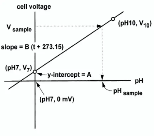
Because pH cells are not ideal, they must be calibrated before use. pH cells are calibrated with solutions having exactly known pH, called buffers.
pH Meter Sensor Installation
Immersion and insertion applications
- If a pH sensor is to be inserted directly into a pipe, choose a location that is always flooded.
- So long as a liquid film provides a conductive path between the glass membrane and the reference junction, the sensor will produce a reading. The reading, however, is the pH of the film, not the process liquid. If the film dries out, the sensor will appear to have failed.
- Always consider the velocity and density of the liquid flowing past the sensor.
- A dense liquid moving at a high flow rate can deform the sensor, particularly if it extends some distance into the stream.
- Install pH sensors with the bulb down, within 80° from vertical.
- The potassium chloride and buffer solution inside the glass electrode must completely wet the inside surface of the glass bulb, and there must be a conductive path between the internal reference electrode and the inside glass surface. Installing the electrode bulb pointed up or at an angle too close to the horizontal will break the connection.
- pH sensors need regular calibration and, in some applications, regular cleaning.
- The ease with which the sensor can be removed from the piping should always be considered.
Maintenance of pH Analyzer:
- Maintenance of pH measurement systems involves mostly cleaning and calibrating the pH sensor. The analyzer itself requires almost no maintenance.
- CLEANING pH SENSORS: The frequency at which a sensor should be inspected and cleaned can be determined only by experience. If the process liquid coats or fouls the sensor, frequent cleaning may be necessary. If the process does not contain a high level of suspended solids, the need for regular cleaning will be less.
- CALIBRATING pH SENSORS: The frequency at which sensors should be calibrated can be determined only by experience.
- However, many factors influence the calibration frequency are:
- Sensors installed in dirty or corrosive process streams usually require more frequent calibration than sensors used in clean water.
- Sensors measuring extreme pH values, particularly high pH, also require more frequent calibration than sensors measuring mid-range pH.
Noise pH readings in pH Meters
Noise is a rapid, random fluctuation in a signal. Noisy pH readings can have many causes.
- The pH signal is high impedance, so it is susceptible to environmental noise. Problems with environmental noise can also be minimized by pre-amplifying the signal at the sensor.
- The impedance of the glass electrode increases as temperature decreases. An increase in impedance caused by a cold sample might be contributing to the noise.
- A plugged or depleted liquid junction can also be a source of noise.
- Noisy readings, particularly if accompanied by offsets that disappear when the sample is electrically isolated from the process piping, can be a symptom of ground loops.
- Noise can be a severe problem when measuring the pH of high-purity water. pH readings in high-purity water are also flow-sensitive. High flow can produce very noisy readings as well as offsets as great as 0.5 pH units. The problem is likely caused by variations in the electrical potential at the surface of the junction plug. The fluctuating potentials are related to the flow of filling solution through the junction pores.
Drift in pH Analyzers
Drift is a gradual increase or decrease in a signal not caused by an actual change in the process liquid.
- Temperature changes can cause drift.
- Dirty sensors often produce pH readings that drift.
- The memory of past junction potentials can also lead to drift.
Ground Loops in pH meters
A ground loop exists when a circuit is connected to the earth’s ground at two or more points. Because the potential of the earth varies from point to point, two or more connections to the ground cause currents to flow. If the current flows through a signal-carrying wire, the result is a noisy, offset signal.
Procedure to check for ground loops
- Remove the pH sensor from the process liquid.
- Calibrate the sensor in buffers. Be sure there is no direct electrical connection between the container holding the buffer and the process liquid or piping.
- Strip back the ends of the heavy gauge wire. Connect one end of the wire to the process piping or better, place it in the process liquid. Place the other end of the wire in the container with the buffer and sensor. The wire makes an electrical connection between the process and the sensor.
- If the pH reading changes or becomes noisy after making the connection, a ground loop exists. If no symptoms develop a ground loop probably does not exist.
Recommendation for Accurate pH Measurement in pH Analyzers
- Correct Electrode Storage: Correct electrode storage maximizes electrode performance and extends the electrode life. Do not store pH electrodes in distilled water. The filling solution will be diluted and the electrode response will be slow.
- Proper Maintenance and Cleaning: Inspect the electrode weekly for scratches, cracks, or salt crystallization. If the readings become slow or drifty, clean the electrode per the manufacturer’s instructions. Excessive cleaning may impair electrode performance and shorten electrode life.
- Stirring: Stir all buffers and samples at a uniform rate to obtain a representative sample measurement and improve electrode response time. Use a magnetic stirrer at a moderate speed. Use a piece of insulating material (e.g. Styrofoam or cardboard) between the stir plate and the beaker to prevent heat transfer.
- Filling Solution Level: The filling solution level must be higher than the sample level to maintain a uniform flow of filling solution. At least 1 inch above sample height is recommended
- Rinsing: Rinsing prevents contamination by carryover on the electrodes. Rinse with de-ionized water or an aliquot of the buffer, standard, or sample. Do not wipe the pH electrode glass bulb. Transfer of static charge onto the glass bulb will result in a slow or drifty response.
- pH Buffers: pH Buffers should be accurate and free of contamination. Keep the buffer or standard bottle tightly sealed. Do not reuse buffers and standards. Verify the buffer or standard is within the expiration date before use. If trouble arises always use fresh buffers.
- Temperature: To account for pH slope, buffer, and sample changes, use a separate or integrated automatic temperature compensation probe (ATC). Calibrate at least once a day with 2 or 3 buffers that bracket the expected sample range. Choose pH buffers that are no more than 3 pH units or no less than 1 pH unit apart.
- Electrode Cleaning: After any of these cleaning procedures, drain and refill the reference chamber and soak the electrode in storage solution (or pH 7 buffer) for one hour.
- General – Soak the electrode in 0.1M HCl or 0.1M HNO3 for half an hour.
- A second general cleaning procedure involves soaking the electrode in a 1:10 dilution of household laundry bleach in a 0.1-0.5% liquid detergent solution in hot water with vigorous stirring for 15 minutes.
- Removal of Deposits:
- Protein- Soak the electrode in 1% pepsin in 0.1M HCl for 15 minutes.
- Inorganic- Soak the electrode in 0.1M tetrasodium EDTA solution for 15 minutes.
- Grease & Oil- Rinse the electrode with a mild detergent of methanol solution.
Applications of pH Analyzers/pH Meters
Copper Floatation Process (Fig. 8):
- Crushed ore (containing 1 to 2% copper), along with water and a lime slurry, is fed into a ball mill.
- This rotating drum contains steel balls that further crush the ore to a fine powder.
- When the ore/lime slurry emerges from the mill, it is fed to a rake classifier.
- Particles that are too large to pass from the classifier are returned to the mill, while the overflow is discharged to flotation cells.
- Air is injected into the flotation cells, and foaming agents are added, creating a froth.
- Copper ore particles, due to their relatively lightweight, become a part of this froth, while heavier particles, such as iron ore, do not.
- The copper-rich froth, containing 20 to 40% copper, is then separated from the solution for further processing.
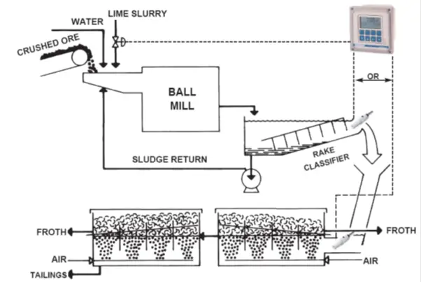
Principle: As seen above, rich copper ore is separated from crude copper sulfide ore by means of a flotation process, that takes advantage of the physical (as opposed to chemical) properties of small copper ore particles. To maximize the yield of copper, pH control is necessary for the flotation tanks.
pH CONTROL:
- The condition of the froth is directly dependent on pH.
- The flow rate of lime slurry is therefore regulated to keep the pH within the acceptable range.
- If pH is too low, iron will be entrapped as well as copper, decreasing the value of the copper ultimately recovered.
- If too much lime is added, the result is a dilute froth that requires additional concentration in later stages, increasing the operating costs and wasting time.
Gold Ore Processing Using Cyanide (Fig. 9):
- The heap-leaching solution continuously flows over the ore and may be collected and stored in a pond.
- In heap leaching, the carbon is usually held in a fixed column and the solution is passed over the columns repeatedly.
- The gold cyanide is typically separated from the pregnant liquor using carbon adsorption beds.
- The activated carbon adsorbs the gold cyanide complex on the surface of the carbon particles.
- The gold cyanide in the pregnant solution is adsorbed on granular activated carbon inside the carbon in pulp (CIP) tanks.
- Later, the carbon is washed with hot caustic to remove the gold and then rinsed with acid to regenerate the carbon particles for reuse.
- The coarse-laden carbon particles are screened out of the last tank, and washed with caustic to remove the gold cyanide, and the gold metal is produced using a process called electrowinning.
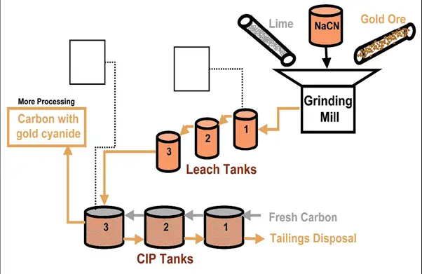
- When pregnant liquor contains large amounts of silver, and zinc, precipitation may be used instead of carbon adsorption.
- Zinc precipitation liberates the gold metal by adding zinc metal to the solution, which rapidly displaces the gold in the Au(CN)2.
- Once the solution has been depleted of the gold cyanide, it is called barren solution and is returned to the heap, to continue the leaching process.
- Long-term use of the solution will cause the pH of the solution to change, so makeup caustic and/or lime may be added periodically to the barren solution. This process occurs so slowly that online instrumentation is rarely required.
- Due to the rapid reactions taking place in an agitated leach process, automatic pH control is strongly recommended.
pH MEASUREMENT:
- pH is controlled between 11 and 12 during the leaching process.
- pH values below 11 favor the formation of HCN, hydrogen cyanide.
- Hydrogen cyanide is a colorless and poisonous gas that, if released due to lower pH values, can quickly become deadly.
- Cyanide is also a relatively expensive chemical, so small losses in heap leaching can amount to large makeup costs over time.
- Gas leaks into the environment are a risk to the mine personnel and future liability to the mining corporation that can be avoided using pH measurement.
Boiler Flue Gas-Scrubbing System:
- After fly ash removal, the flue gas is bubbled through the scrubber, and the slurry is added from above.
- Water absorbs the SO2 gas which reacts to form sulfite ions. These ions can further react with dissolved oxygen to yield calcium sulfate.
- The scrubbed gas may be heated, to prevent condensation, and then discharged in a stack.
- Spent scrubbing liquids are sent to a clarifier, where much of the water is reused.
- Spent solids are removed in a heavy slurry to a settling pond. The water (with makeup fresh water, as needed) is returned to the scrubber.
- Both lime and limestone can be used to combine with the sulfite ions to form calcium sulfate (gypsum). Neither dissolves well in water and therefore, both are pumped in slurry form to the scrubber tower.
- A pH sensor in a recirculating tank is used to control the feed of solid lime or limestone.
- Lime slurry is more alkaline, having a pH of 12.5 while limestone slurry is roughly neutral. A lime-based system will therefore add more lime when the pH drops below 12 and a limestone-based system will be controlled around 7.
- Unless one or the other is added, the SO2 gas will quickly drive the pH acidic. The calcium compounds produced in scrubbers tend to accumulate in recirculation loops and can cause a buildup of scale.
- Scale on the spray nozzles affects the atomization of the water droplets and reduces the scrubbing efficiency. Scale on the return piping reduces the flow rate and changes the thermal balance of the system.
- The tendency to scale is limited by additives such as chelating agents and phosphates, but these additives are generally only effective at higher pH levels.
- pH control is necessary to forestall the start of scaling, as it is much easier to prevent scaling than to remove it.
Reverse Osmosis (Fig. 10):
pH control protects Membranes in Reverse Osmosis
Reverse osmosis is a technique for removing dissolved solids from filtered raw water. It is used in a variety of industries to condition water for plant use, or as a first step in the demineralization process.
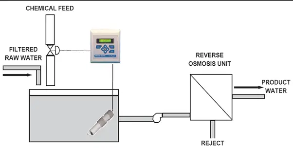
- The key factor in reverse osmosis is the condition of the semi-permeable membrane.
- A typical membrane material is cellulose acetate, which tends to be degraded by alkaline (high pH) water, resulting in a loss of efficiency.
- Precipitation can occur on the process side of the membrane when the raw water contains calcium harness and its pH is in the alkaline range.
- To protect the membrane and avoid scaling, the pH of alkaline raw water can be adjusted to the acid side (pH 5.5 is the usual target).
- The control action is not difficult since raw water does not typically tend to have major pH fluctuations or load changes (changes in the titration curve).
- To accommodate changes in flow rate, flow measurement can be used to trim the pH control.
pH Control -Sugar Plants (Fig. 11):
- Processed sugar is refined from raw sugar cane.
- The process includes the following steps:
- wash, crush (or shred), extract (i.e. dissolve in warm water), treat with lime, carbonate, filter, add sulfur dioxide, concentrate, crystallize, and dry. The steps in bold are most critical to the final product and require continuous pH control.
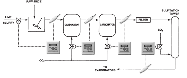
Liming:
Alkaline (whitish lime particles suspended in water) is automatically injected to raise the pH of the raw juice to 11-11.5.
The purpose of adding lime (Calcium Oxide) is threefold:-
- Neutralize acids in the cane, thereby preventing the sucrose from turning into starch (hydrolysis) or other forms of sugar (inversion).
- Precipitate the organic acids into salts for subsequent removal.
- Keep foreign matter (insoluble organics, proteins, etc.) in suspension until a filtration process can remove them.
Carbonation:
- All traces of lime must be removed before the concentration step to prevent scale buildup.
- Carbon dioxide, therefore, is added to the juice to precipitate the lime as less soluble calcium carbonate (limestone), which also tends to capture other impurities during precipitation.
- Carbon dioxide is usually added in several stages to avoid an unmanageable type of precipitate that can develop in single-stage carbonation.
- At each stage, the pH is measured and carbon dioxide is automatically injected.
- By the last stage, the pH should be reduced to about 9.
- After carbonation, the juice is filtered to remove all traces of solid particles before flowing to the sulfidation tower.
Addition of Sulfur Dioxide (Sulfidation):
- Sulfur dioxide is automatically added to the juice to lower the pH to roughly 5-6 before it goes on to the evaporators.
- The sulfur dioxide also bleaches the juice to improve flavor and texture.
- Without this step, an alkaline juice would be produced, the sugar crystals would stick together due to excess moisture, and the product would have an undesirable taste.
Leak Detection -Using pH measurement (Fig. 12):
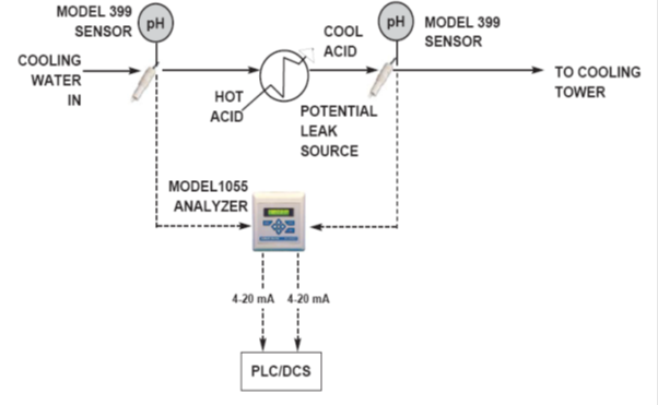
- All industries from food and beverage to chemical processing use heat exchangers, condensers, or jacketed vessels.
- Leakage of the process into the cooling water represents a loss of product and can be a source of fouling or corrosion in the cooling water system.
- Conversely, leakage of the cooling water into the process can be a source of contamination, which is not acceptable.
- Differential pH involves using two pH analyzers, one before the potential leak source and one after. The difference in pH is measured and used to detect the leak.
- The reason for using differential pH is to cancel out variations in the sample pH.
- Ideally, when no leak is occurring the differential pH would read zero.
- In a real sense, two factors must be taken into account before applying differential pH. The first is the rate at which the sample pH changes and the second is the transit time, which is the time it takes the sample to pass through the potential leak source

Dear Mam/Sir,
Greetings of the day!!
Our organization required pH sensor in line. Our media composition is media composition – it will be a chemical composition having water (i) 9.5 to 10.5 % (ii) 20 to 25%