
Start-Prof is a part of PASS software suite for piping stress analysis, hydraulics analysis, boiler & pressure vessel, heat exchanger, column, tank design & stress analysis is available worldwide since 2018.
Article consists of 2 parts:
- Part 1. Unrestrained, Totally Restrained and Partially Restrained Pipes. Bourdon Effect
- Part 2. Restrained and Unrestrained Zones in the Buried Pipelines. Interpretation of Strength Criteria in ASME B31.4 and B31.8
ASME B31.4 and B31.8 codes divide pipes into restrained and unrestrained. Which part of pipe is restrained and which is not? Many engineers have a misconception about this. We will explain the difference and suggest new universal strength criteria, which cover both restrained and unrestrained pipes.
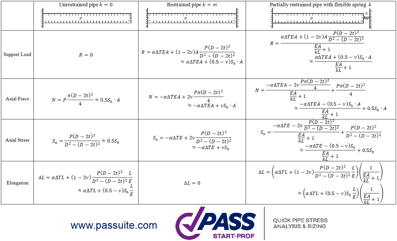
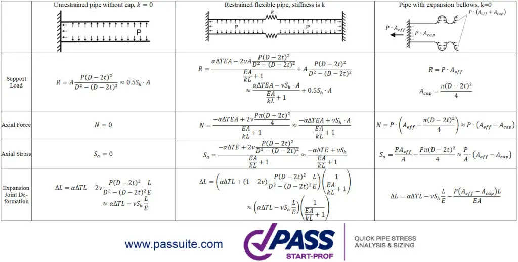
Before we begin, let’s say that actually, there are three types of pipe behavior instead of two described in ASME B31.4 and B31.8 codes:
- Unrestrained
- Totally Restrained
- Partially Restrained
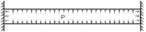
Unrestrained Pipe
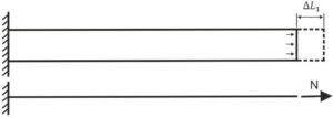
Unrestrained pipe expansion from the pressure load consists of two parts. The first part is the expansion due to the pressure load on the end cap. The second part is pipe shortening due to Hook’s law.
Pipe expansion from the pressure load on the end cap is:
![]()
L – Pipe Length
E – Modulus of Elasticity
Pipe cross-section area is
![]()
D – Pipe Outer Diameter
t – Pipe Wall Thickness
N – Axial Force in the Pipe
Axial force N is equal to the force acting on cap
![]()
P – Internal Pressure
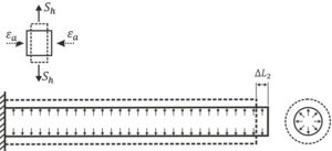
Pipe expansion will be
![]()
Sh – Hoop Stress in the Pipe
![]()
According to Hooke’s law the axial deformation of the pipe under axial stress is:
![]()
v – Poisson’s Ratio
Pipe shortening due to internal pressure:
![]()
Total pipe expansion from pressure load is
![]()
If we add thermal expansion the equation will be:
![]()
![]() – Temperature Difference between Installation and Operation temperature
– Temperature Difference between Installation and Operation temperature
![]() – Coefficient of thermal expansion
– Coefficient of thermal expansion
Longitudinal stress caused by internal pressure is
![]()
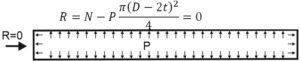
If the left end is connected to pressure vessel nozzle or rotary equipment, then axial force in the equipment nozzle will be N as calculated above. But when equipment manufacturers calculate allowable loads, they assume that nozzle has end cap and vessel is under pressure. This means that axial stress caused by pressure is already included into allowable loads and should not be considered twice.
This means that we must exclude the pressure thrust load from axial force to calculate the support load that can be compared to allowable load on nozzle. To do this we must assume that pipe has two caps on the both ends. In this case the support load R will be equal to internal force N minus thrust force on the end cap, i.e. zero
A strength criterion for unrestrained pipe is:
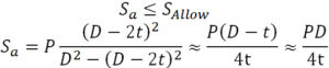
Sallow ‑ Allowable stress.
If we add here bending stress and axial stress from loads other than pressure, we get
![]()
If we want to add torsion stress, we should calculate equivalent stress:
![]()
Allowable stress value depends on the code. Usually it is Sh or 0.75Sy for sustained loads, kSh or 0.9Sy for occasional loads, 0.9Sy…Sy for test state. Occasional load factor k=1.15…1.8 depends on selected code. Sy is yield stress, Sh – code allowable stress at operating temperature.
Thermal expansion has no effect on unrestrained piping systems, i.e. this equation usually used for sustained and occasional stress check in piping systems from pressure, weight and other force-based loads.
The code equations were created for manual calculation. But now most of pipe stress analysis software can consider Bourdon effect. This means that code equations should be modified to match the current level of technology.
If axial force N is calculated using software that considers Bourdon effect, then we should subtract PD/4t value from axial force otherwise it will be included twice:
![]()
The criteria for software analysis where M and N calculated with Bourdon effect should be just:
![]()
This has been already done in ASME B31.3 for Process Piping, GOST 32388 for Process Piping, GOST 55596 for District Heating Networks, SNiP 2.05.06-85 for Gas and Oil Pipelines, but still not fixed in all other ASME B31.X and EN 13480 codes.
Totally Restrained Pipe
For a restrained pipe with two anchors on both ends, thermal expansion should be zero
![]()
The axial force required to compress the pipe back to its original length can be calculated from this equation:
![]()
Therefore support load should be:
![]()
After substitution the thermal expansion equation we got final support load for restrained pipe:
![]()
The value of axial force can be obtained from the equilibrium conditions near the anchor. Axial force is equal to reaction in anchor minus the pressure thrust force that is received by anchor and doesn’t acting on the pipe:
![]()
Final equation for axial force in restrained pipe is
![]()
Axial stress in the restrained pipe will be
![]()
A strength criterion for totally restrained pipe is:
![]()
If we add here bending stress M/Z and axial stress N/A from loads other than pressure, we get
![]()
If we want also consider torsion and hoop stress, we should use the equivalent stress equations like described for unrestraint pipes.
If axial force is calculated using software that considers Bourdon effect, then we should subtract pressure axial stress:
![]()
The criteria for software where M and N calculated with Bourdon effect and thermal expansion should be:
![]()
A criterion is the same as for unrestrained pipes, but allowable stress is usually 0.8Sy…1.0Sy to prevent the Yielding through all pipe length.
The maximum temperature difference for fully restrained pipe, ignoring longitudinal buckling effect, can be found by equation:
![]()
If pressure is zero, this value is about 80…110 C for steel pipes.
Partially Restrained Pipe
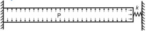
If we add flexible spring instead of rigid anchor on the right end of the pipe, we will get the third pipe condition – partially restrained.
We will pass the derivation of equations process and just show the final equations in table below.
The strength criteria for partially restrained pipes should be
- From sustained primary loads:
![]()
- From occasional primary loads
![]()
- From both primary and secondary loads acting simultaneously
![]()
Primary Loads – are force driven not self-limiting loads like weight, pressure, relief valve thrust, wind, etc.
Secondary Loads – are displacement driven self-limiting loads like thermal expansion, anchor movements, support or soil settlement, etc.
Unrestrained and fully restrained pipe conditions can be easily calculated manually, but third condition require using of pipe stress analysis software, because spring stiffness k depends on connected pipes.
Bourdon Effect Model in PASS/Start-Prof
Now I will explain how PASS/Start-Prof software considers pressure Bourdon effect in arbitrary piping model. Start-Prof model the pressure loads consist of two parts.
Firstly, Start-Prof adds pressure thrust force on each end of the pipe.
![]()
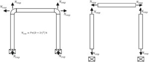
Secondly, Start-Prof adds axial deformation for each pipe. It equal to pipe thermal expansion minus pressure shortening.
![]()
The combination of these two loads allows to model correctly any type of piping: unrestrained, restrained, and partially restrained.
Bourdon effect makes a significant contribution to the support loads, displacements, and stresses for
- High pressure piping
- Plastic piping (PE, PP, PB, PVC)
- FRP/GRP/GRE piping
Start-Prof always preforms analysis with Bourdon effect, it is non-disabling function.
Dear Mr. Matveev,
Thank you for sharing useful articles.
Can you please explain why at the end, in deformation calculation of each pipe, the pipe expansion due to the internal pressure (0.5*Sh*L/E) was not considered?
Best regards
It is considered. The Ncap forces are applied for each pipe and it cause the whole piping system deformation
yes, my bad 🙂
thank you a lot