
Lines play an important role in the technical and engineering industry. Explaining a complex drawing in words is impossible and hence, engineering drawing has become the worldwide language of engineers, designers, technicians, scientists, and craftsmen. The shape, scale, and interrelation of a complex thing can easily be transmitted using engineering drawings. Every engineering drawing has various types of lines in it and so, lines are a major part of the graphic language.
Lines used in any engineering drawing may be straight or curved. Lines are defined as elements with no breadth but unlimited length (magnitude). Lines locate two points that are not in the same location but fall along the line. A straight line denotes the shortest distance between two points.
Lines can be drawn in any direction. Straight and curved lines are parallel when the shortest distance between them remains constant.
Again, lines are differentiated as thick lines (0.6 mm thickness), thin lines (0.3 mm thick), Continuous lines, dashed lines, freehand lines, zigzag lines, chain lines, etc. In this article, we will learn the various types of lines that are widely used in engineering drawings.
Types of Lines for Engineering and Technical Drawings
There are 12 main types of lines usually used in engineering drawing while drafting. They are:
- Visible lines
- Hidden lines
- Section lines
- Center lines
- Dimension lines
- Extension lines
- Leader lines
- Cutting plane lines
- Break lines
- Phantom lines
- Borderlines
- Arrowheads
Visible Lines
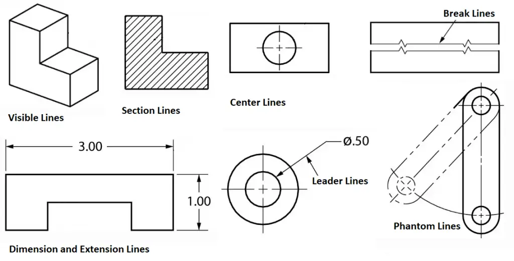
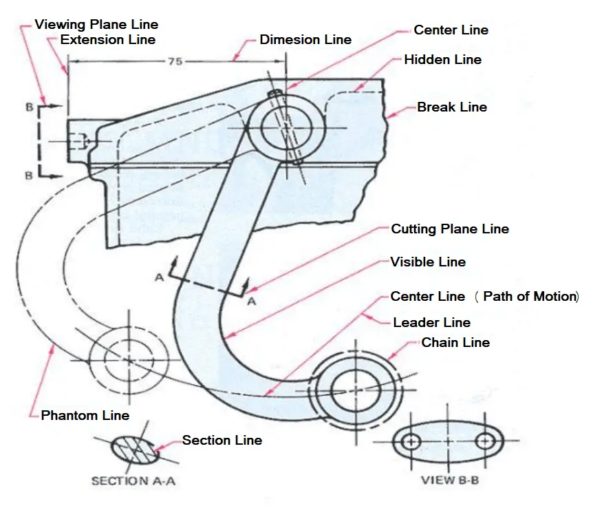
They are dark and thick lines of any engineering design drawing. Also known as object lines, visible lines define the features that will be clearly visible in a particular view. They define the outline or contour of the object. All thick lines are usually drawn 0.6 mm thick. Refer to Fig. 1 which gives an example of various types of lines used in technical and engineering drawing.
Uses: Visible lines represent the visible edges and outlines of objects.
Hidden Lines
Hidden lines are light, dashed, narrow, and short. They provide features that can not be seen in a particular view but are provided to clarify some specific features. To start and end hidden lines, a dash is always used except when a hidden line starts or ends at a parallel visible or hidden line. Dashes should meet in the corners. All thin lines are of 0.3 mm thickness. Sometimes hidden lines can be omitted.
Uses: Hidden lines represent edges or boundaries that are not visible from the current view, such as hidden features inside an object.
Section Lines
Section lines are thin lines drawn at a 45-degree angle. They are also called hatch lines. In any sectional view, section lines indicate the material that has been cut through.
Uses: It represents the surface that has been cut in a sectional view, typically shown as hatching.
Center Lines
Center lines in an engineering drawing show the center of a round or cylindrical shape. The line is drawn using a thin line with alternating long and short dashes. Long dashes are used to begin and terminate center lines. This is also sometimes known as long/short-dashed thin lines.
At the center point, the center lines must intersect by crossing either the long or short dashes. They should continue a short distance beyond the object or feature. To represent that two or more features are in the same plane, center lines can be joined within a single view. The center lines are not meant to cross the space between views.
Uses: A center line Indicates the center of circles, arcs, or symmetrical parts. Represented by a long dash followed by a short dash.
Dimension Lines
As the name suggests, dimension lines represent the dimensions or sizes of components in an engineering drawing. They are represented by thin lines with arrowheads at the ends that are broken along their length to make room for the dimension number. The dimension (length) is mentioned clearly. Refer to Fig. 2 which shows typical dimension lines used in Engineering Drawings.
Extension Lines
Extension lines which are added using thin lines determine the extent of a dimension. Sometimes, extension lines are used to demonstrate the extension of a surface to a theoretical intersection.
Leader Lines
Leader lines are used to mention a specific note to a feature on a drawing, as well as to direct dimensions, symbols, item numbers, and part numbers. they are added using thin lines.
The main features of leader lines are:
- Usually drawn at 30, 45, and 60 degrees.
- It has a short shoulder at one end that begins at the center of the vertical height of the text and a standard dimension arrowhead at the other end that touches the feature.
- Leader lines should not cross one another and should not be overly long.
- Leader lines are not drawn in vertical or horizontal orientation.
- Dimension lines, section lines, and extension lines should not be parallel to leader lines.
Uses: Connects a note, dimension, or reference to a specific feature on the drawing.
Cutting Plane Lines
Cutting plane lines are thick broken intermittent lines with small 90-degree arrowheads. These type of lines indicates when a section is mentally cut in half to better perceive the internal detail. These types of lines are also sometimes known as viewing plane lines.
Uses: It shows where a sectional view is taken.
Break Lines
Break Lines in engineering drawings are very important and are used to separate sections for clarity or to shorten a section. There are three types of break lines, each with a distinct line weight:
- Short Break Lines: Short break lines are denoted by a thick wavy line and are used to break the edge or surface of a part to reveal a concealed surface.
- Long Break Lines: Long, thin lines are used as long break lines to indicate that the center section of an object has been removed so that it can be drawn on a smaller piece of paper.
- Cylindrical Break Lines: To depict spherical parts that have been broken in half to better clarify the print or to shorten the object’s length, thin lines are used as cylindrical break lines.
Uses: They are used to show that a portion of an object has been removed or that the object continues beyond the current view.
Phantom Lines
Phantom Lines are thin lines composed of long dashes alternated with pairs of small dashes. This type of line in engineering drawings serves the following purposes:
- They depict the alternate location of moving parts.
- They demonstrate the relationship between elements that fit together.
- They demonstrate repetitive detail.
Uses: Indicates alternate positions of moving parts, adjacent positions, or repeated details.
Border Lines
Thick and continuous lines that show the drawing’s boundaries or divide different objects drawn on the same sheet are known as border lines. They are also used to distinguish the title block from the body of the illustration.
There are some other types of technical drawings as listed below:
Symmetry Lines:
- Symmetry lines are imaginary lines that are believed to pass through the centers of areas, shapes, objects, and drawn structures. The symmetry lines divide the object into equal and similar-looking parts means the object has symmetry with respect to the symmetry line.
- Uses: Indicates that a drawing or object is symmetrical about a particular axis.
- Significance: Symmetry lines are important for ensuring that symmetrical parts are correctly represented and that features are mirrored accurately across the axis. This is particularly useful in mechanical and architectural designs where symmetry is a key aspect.
Chain Lines:
- Chain lines are broken or spaced parallel lines used to indicate pitch lines (which show the pitch of gear or sprocket teeth), center lines, developed views, or features in front of a cutting plane. Typically, chain lines are placed at the beginning and end of long dashes, at center points for center lines, in dimensioning, or for other specific purposes.
- Uses: Used to indicate pitch lines (for gears or threads), center lines, cutting planes, or paths of motion.
Arrowheads
Arrowheads are used to end dimension lines, leader lines, cutting-plane lines, and viewing plane lines. They are drawn three times the length of the width. Arrowheads can be filled or not filled.
Line Precedence
When two or more lines appear in the same position, the lines that are the least relevant are removed. Lines in engineering drawings are drawn in the following order of precedence/importance:
- Cutting plane line
- Visible line
- Hidden line
- Centerline
All the above lines are usually predefined in most CAD Software packages as layers. Depending on the layer chosen, the line will be inserted in the drawing and will be visible in a certain way. However, most drafting companies make their own custom layers with different colors to distinguish them from one another.
Types of Lines in Engineering Drawing as per ISO 128-2
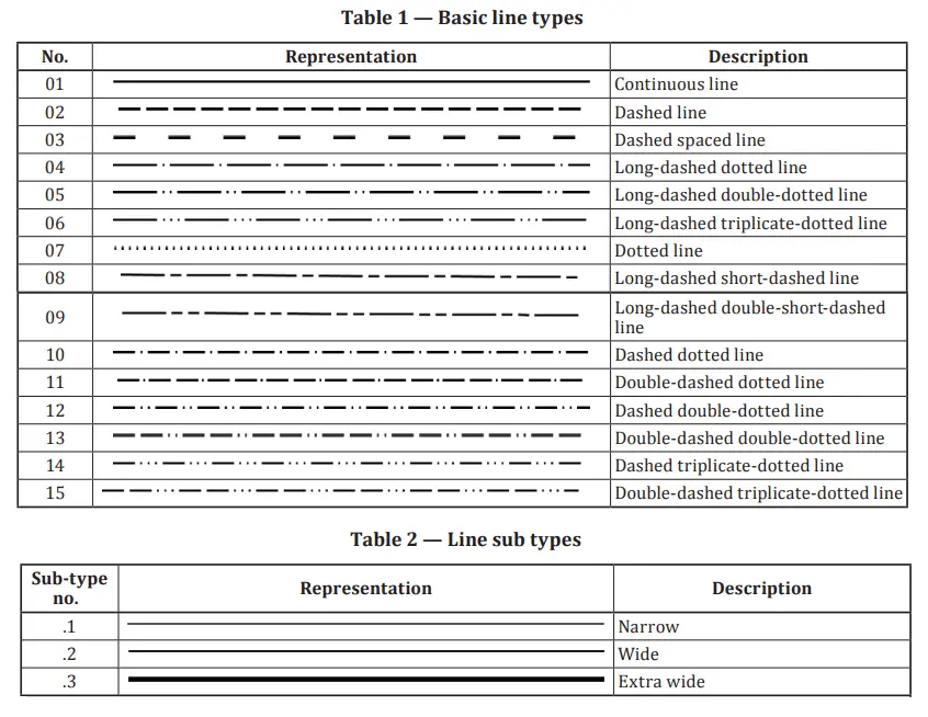
The international standard ISO 128 Part 2 provides the basic conventions for lines used in engineering technical drawings. The standard establishes the line types extensively used in engineering drawings for producing diagrams, plans, or maps. ISO 128-2 also provides the designations and configurations of all types of lines, as well as general rules for line draughting.
Referring to ISO 128-2, there are 15 basic line types and three line subtypes as represented in the following image (Fig. 3):
Technical Line Dimensions:
The width of engineering drawing lines can be one of the following depending on the type and size of the technical drawing.
- 0.13 mm;
- 0.18 mm;
- 0.25 mm;
- 0.35 mm;
- 0.5 mm;
- 0.7 mm;
- 1.0 mm;
- 1.4 mm;
- 2.0 mm.
Note that the line width of any one line must be constant throughout the complete line. If you are a designer and wish to master all the types of lines used in engineering drawing, ISO 128-Part 2 is a must-read for you.
In recent times, due to technological advancement, most of the engineering drawings are produced by CAD software packages. Most of the above-mentioned line types are predefined in CAD Software packages as layers so you don’t have to worry about the uniformity of the line widths. Based on the line requirement of the engineering drawing you can easily choose the necessary layer to display the line in a certain way. Customization of line types is also possible in these CAD software programs.
Lines are Soo crazy to know
We are looking for a tanks farm storage tanks construction company, we may come in direct cooperate in construct a project petroleum product storage tanks of more than 500,000 tonne in Republic of Yemen
We expect your help to get some companies Email addresses to contact
Best regards
Eng. Khaled
Well explained. As an engineering technician it is very useful for me to know the types of lines.Thanks ank hope for more.
Wagwan my brothers