What is the Stress Intensification Factor or SIF?
The term SIF (Stress Intensification Factor) is too confusing for many piping engineers. That’s why the following article is taken to explain the bend SIFs in simple language. Every piping Engineer who possesses a little basic of the Piping Stress Analysis theory must be aware of the term SIF or Stress Intensification Factor.
The term SIF indicates a multiplier of Bending and Torsional stresses. This Intensifier acts locally on a piping Component ( tees, elbows, bends, Olets, etc.) and Its value depends on component geometry. The minimum value of the SIF is 1.0. It is widely used by piping stress engineers in places where the actual stress calculation is quite difficult due to its difficult geometry (Varying thickness, cross-section, curvature, etc.) as, unlike straight Pipes, the simple Beam theory is not applicable. So in this situation, it is required to assume additional stresses by suitably incorporating an SIF. The following article will provide an example of SIF calculation of piping elbow or piping bends following process piping code ASME B31.3.
Stress Intensification Factor for a Piping Bend/Elbow
In layman’s language, the SIF of a bend or elbow can be defined as the ratio of bending stress of an elbow to that of a straight pipe of the same diameter and thickness when subjected to the same bending moment. Whenever the same bending moment is applied to a bend because of ovalization the bending stress of the elbow will be much higher than that of a straight pipe. That is why the SIF value will always be greater than or equal to 1.0 (for straight pipe).
The process piping code ASME B31J (Appendix D of ASME B31.3 till edition 2018 of ASME B31.3) provides a simple formula to calculate the SIF of a bend or elbow. As per that code
- SIFin-plane = 0.9 / h(2/3)
- SIFout-plane = 0.75 / h(2/3)
Here h=T R1 / r22
h =Flexibility characteristics, dimensionless
- T =Nominal wall thickness of bend, in
- R1 =Bend radius, in
- r2 =Mean radius of the matching pipe, in
In-plane and Out-plane SIF
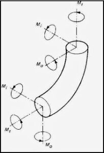
The in-plane and out-plane SIF concept for a bend can be obtained from the attached figure from code or in layman’s language the same can be explained as follows:
The in-plane bending moment is the bending moment that causes the elbow to close or open in the plane formed by two limbs of the elbow. In a similar way, the out-plane bending moment can be defined as the bending moment that causes one limb of the elbow to move out of the plane keeping another limb steady.
From the above-mentioned equations, the following can be interpreted: For the same pipe size and same pipe thickness
- A short-radius elbow has more SIF as compared to a long-radius elbow.
- With an increase in the bend radius, the SIF decreases and finally reaches 1.0 for the straight pipe.
- The SIF for a 45-degree elbow and a 90-degree elbow is the same and the bend radius is the same.
- With an increase in nominal pipe thickness or schedule, the SIF of a bend (90-degree) keeps on decreasing till its value is equal to 1.0.
Few more Resources for you..
How to use ASME B31J-2017 and FEM for SIF and k-factors for Stress Analysis
Importance & Impact of Stress Intensification Factor (SIF): A Presentation
Piping Stress Analysis Basics
Piping Design and Layout Basics
Piping Materials Basics


It’s really nice explanation…Thanks lot…
HI. I LIKED YOUR BLOG..
I am very much interested to learn about oil and gas piping design
Are you available to perform calculations of forces (internal and external) at the elbows of 24″ Dia (609.6 mm) piping carrying air at a very high velocity?