
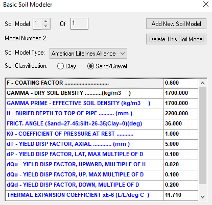
While performing buried or underground pipeline stress analysis, soil parameters must be entered in Caesar II software to help the software generate the bilinear restraints. The usual parameters that are required as the software input are presented in Fig. 1. Note that these parameters will vary depending on the soil type, soil compaction type, etc. Some typical values shown in Fig. 1 are considered for a case study to study the impact of coating factor.
What is Pipeline Coating?
Pipeline coating refers to the application of protective materials on the surface of pipelines to prevent corrosion, mechanical damage, and other forms of deterioration. These coatings serve several important purposes:
- Corrosion Protection
- Mechanical Protection
- Insulation
- Environmental Protection
Types of Pipeline Coatings
There are several types of pipeline coatings available, each designed to address specific requirements and challenges. Some common types include:
1. Fusion-Bonded Epoxy (FBE) Pipeline Coatings:
FBE coatings are thermosetting resins that are applied to the surface of the pipeline and then heat-cured to form a hard, protective layer. They provide excellent corrosion resistance and are commonly used for both onshore and offshore pipelines.
2. Three-Layer Polyethylene (3LPE) and Three-Layer Polypropylene (3LPP) Coatings:
These coatings consist of a fusion-bonded epoxy primer, a copolymer adhesive layer, and a polyethylene or polypropylene outer layer. They offer good mechanical protection and are often used for buried pipelines.
3. Polyurethane (PU) Coatings:
PU coatings are typically applied as a topcoat over FBE or other primer coatings to provide additional mechanical protection and resistance to abrasion, chemicals, and weathering.
4. Coal Tar Enamel (CTE) Coatings:
CTE coatings are made from coal tar pitch and provide excellent resistance to corrosion, water, and chemicals. However, they are less commonly used today due to environmental concerns associated with coal tar.
5. Concrete Weight Coatings (CWC):
CWC consists of a layer of concrete applied to the pipeline to provide weight for stability and protection against buoyancy, particularly for offshore pipelines.
6. Polyethylene Terephthalate (PET) Wrapping:
PET wrapping involves wrapping the pipeline with a strong, flexible polyester film for mechanical protection and to prevent corrosion.
7. Abrasion Resistant Overcoat (ARO):
ARO coatings are designed to provide extra protection against abrasion and mechanical damage, commonly used in areas where the pipeline is exposed to high levels of wear and tear.
8. Ceramic Epoxy Coatings:
These coatings contain ceramic particles suspended in an epoxy resin matrix, offering enhanced abrasion resistance and durability compared to standard epoxy coatings.
What is Coating Factor?
Coating factor is the pipeline external coating dependent factor that relates the internal friction angle of the soil to the friction angle at the soil-pipe interface. This option will be available during buried pipe stress analysis if American Lifeline Alliance in the Soil Model Type list and Sand/Gravel as the Soil Classification is selected. This is basically a type of friction factor. The coating factors that are used for pipeline coating are provided in Table 1 taking a reference from American Lifeline Alliance document “Guidelines for the Design of Buried Steel Pipe”.
| Pipe External Coating | Coating Factor, F |
| Concrete | 1.0 |
| Coal Tar | 0.9 |
| Rough Steel | 0.8 |
| Smooth Steel | 0.7 |
| Fusion Bonded Epoxy | 0.6 |
| Polyethylene | 0.6 |
Case Study to Find the Impact of Coating Factor
In this case study, we will investigate the impact of coating factor by making a case study of a sample pipeline model. Widely used software Caesar II is used for the case study and the pipeline parameters are considered as follows:
- Governing Code: ASME B31.8
- Pipeline Material: API 5L-X65
- Soil Model Type: American Lifeline Alliance
- Pipeline Design Temperature: 80 Deg. C buried part / 90 Deg. C aboveground part
- Pipeline Design Pressure: 495 Bar
- Pipe Size: 6″
- Fluid Density: 420 Kg/m^3
Typical pipeline route is shown in Fig. 2 below:
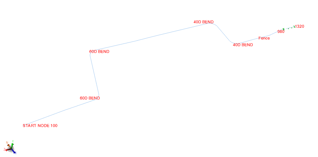
From node 100 to 980 is buried part and from node 980 to 1320 is aboveground part of the pipeline. In this pipeline we will study the following parameters:
- Maximum expansion stress of the system
- Maximum operating stress of the system
- Thermal displacement (Load Case: W+T1+P1) at interface node 980, and
- Thermal displacement at free end node 1320
Results of the Case Study
We have run the Caesar II program considering a coating factors of 0.6, 0.7, 0.8, 0.9 and 1.0. The following table summarizes the impact of various coating factors considered on the stress analysis output results.
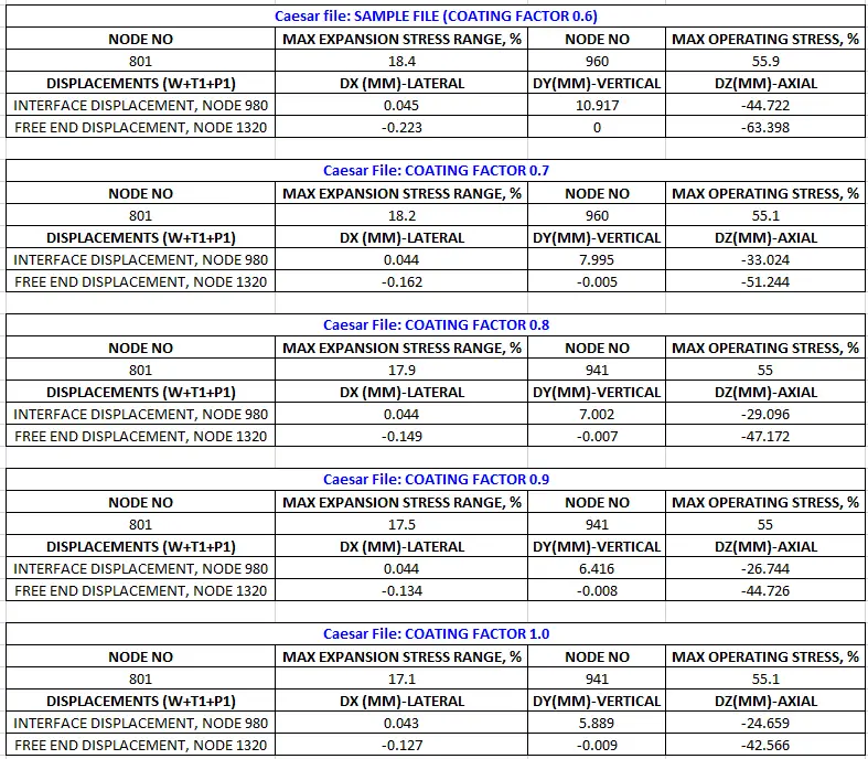
From the above results we can find that,
- With increase in coating factor, both the expansion and operating stress is decreasing.
- With an increase in coating factor, the free thermal movement at the interface node and free end is reducing.
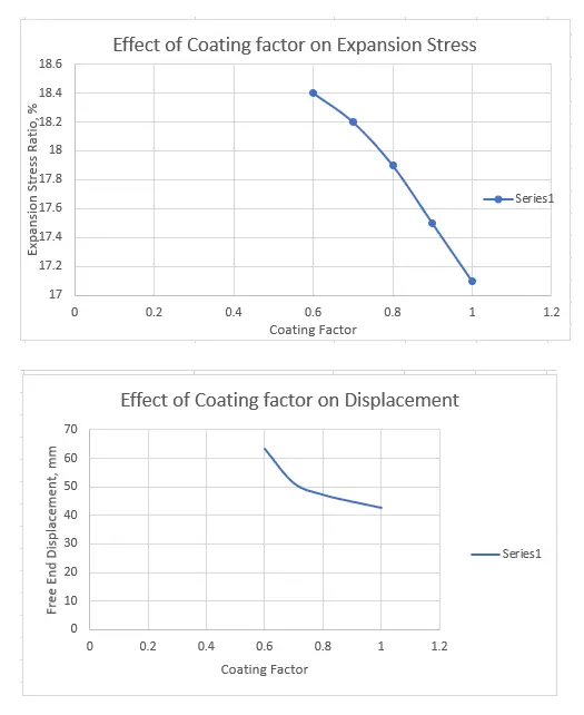
Fig. 3 below shows the results in a graphical plot.
Conclusions
From the above study, it is found that with increase in pipeline coating factor, the friction at the soil-pipe interface is increasing. This increase in friction is adding more resistance to the thermal movement of the pipe and hence a decreased end displacement is found.
However, even though for this specific example, the stress is reducing with increase in coating factor, it may not always be true as friction effect is non-linear and its impact can not be generalized. the effect of friction need to be studied minutely for each system. For more details regarding the impact of friction on pipe/pipeline stress analysis you can refer to the following technical paper by Mr L. C. Peng.