
Fired Heaters, as the name specifies, are obviously heaters or furnaces. They are pieces of equipment used in processing facilities (refineries, power plants, petrochemical complexes, etc.) to heat fluids up to the desired temperature. So, the main purpose of fired heaters is to raise the temperature of the process fluid that flows through the tubes. The heat energy is supplied by combustion fuels. These fall in the static or stationary group of mechanical equipment and are designed based on the API 560 standard. Today we will study the details of Fired Heaters, their components, types, construction features, and maintenance requirements. Let’s dive into the article!
What is a Fired Heater?
A fired heater is a type of industrial equipment designed to generate heat through the combustion of fuel. The heat produced is transferred to a process fluid or other medium, which is then used in various industrial processes. Fired heaters are critical in applications where precise and controlled heating is required, such as in chemical processing, oil refining, and power generation.
Where are Fired Heaters used?
Fired heaters find wide applications throughout chemical industries like refineries, petrochemical and chemical industries, gas processing units, ammonia plants, olefin plants, fertilizer plants, etc. They are termed Feed Preheaters, Cracking Furnaces, Fractionators heaters, Steam reforming heaters, Crude Heaters, etc.
How does a Fired Heater work?
A fired heater works by direct heat transfer from the product of the combustion of fuels. The maximum flame temperature of hydrocarbons burned with stoichiometric air is about 3500 °F (1926 °C). This heat energy is released by combusting fuels into an open space and transferred to the fluids inside tubes, which are ranges along the walls and roofs of the combustion chamber.
What are the different modes of heat transfer in a Fired Heater or Furnace?
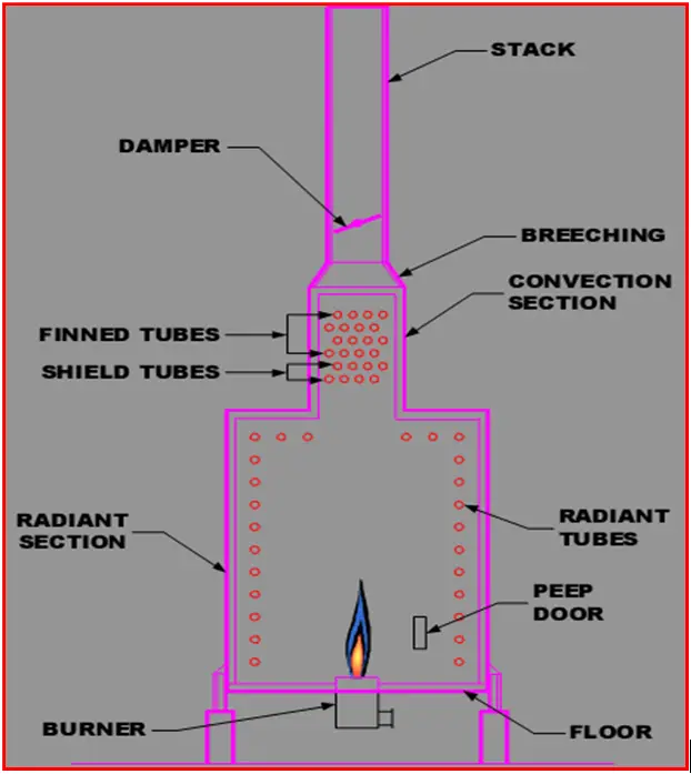
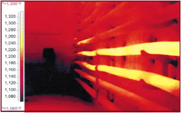
There are different modes of heat transfer that occur in fire heaters. The heat is transferred by direct radiation, convection, and also by reflection from refractory walls lining the chamber. These zones are identified in a typical heater such as that of Fig. 1. In the radiant zone, heat is transferred predominantly (about 90%) by radiation. The convection zone is “out of sight’’ of the burners; although some heat transfer occurs by radiation because the temperature is still high enough, most of the transfer here is by convection mode. The shield section is the name given to the first two rows leading into the convection section.
Components of a Fired Heater
A fired heater consists of:
- Casing
- Tubes
- Return bends
- Tube supports
- Burners
- APH/SAPH
- ID & FD fans
- Pilot
- Radiant, Shield, and Convection zone
- Duct
- Damper
- Stack
- Refractory
- Louvers /Air registers
Casing
The casing of a fired heater acts as the external protective shell, encasing and shielding the internal mechanisms. Its main role is to offer structural support and insulation, thereby minimizing heat loss to the external environment. This outer layer is crucial for maintaining the heater’s durability and effectiveness by retaining the generated heat within the unit.
Tubes
In a fired heater, tubes serve as hollow channels through which hot gases flow, transferring heat to the process fluid. These metal pipes are vital for the thermal exchange, as they enable the combustion gases to deliver their heat to the material being processed, thus enhancing the overall system efficiency.
Return Bends
Return bends are U-shaped tubes that redirect hot gases back through the fired heater. This configuration improves heat transfer efficiency by making sure the combustion gases pass through the system multiple times. By optimizing the path of the gases, return bends help to maximize the heat utilization from the combustion process.
Tube Supports
Tube supports are structural components that stabilize and secure the tubes within the fired heater. They ensure correct spacing and alignment, preventing issues such as tube sagging or damage. Proper support of the tubes is essential for the heater’s longevity and consistent performance.
Burners
Burners are devices within the fired heater that mix fuel and air to create a flame for heat generation. They are crucial for starting and maintaining the combustion process, which directly affects the heater’s efficiency and performance.
APH/SAPH (Air Preheater/Steam Air Preheater)
Air Preheaters (APH) and Steam Air Preheaters (SAPH) are heat exchangers designed to preheat combustion air using residual heat from flue gases. This process boosts overall efficiency by recovering heat that would otherwise be wasted, improving the heater’s energy performance.
ID & FD Fans (Induced Draft & Forced Draft Fans)
Induced Draft (ID) and Forced Draft (FD) fans manage the movement of air and gases within the fired heater. These fans are essential for balancing air and fuel supply, ensuring effective combustion, and contributing to the heating system’s overall efficiency.
Pilot
The pilot flame is a small flame that ignites the main burners when the fired heater starts up. It plays a key role in initiating the combustion process in the main burners, ensuring a stable and controlled ignition.
Radiant, Shield, and Convection Zones
The fired heater is divided into different zones: radiant, shield, and convection. Radiant zones absorb and emit heat, shield zones protect sensitive parts, and convection zones enhance heat transfer efficiency, each contributing uniquely to the heat transfer process.
Duct
Ducts are channels that direct combustion gases from the burners to the heat exchanger. They are essential for controlling the flow of hot gases within the system, ensuring efficient and regulated movement throughout the heater.
Damper
Dampers are adjustable plates or valves that control the airflow within the fired heater. By regulating the airflow, dampers help manage the intensity of combustion, enabling operators to maintain optimal operating conditions for efficient and controlled combustion.
Stack
The stack is a vertical structure that allows the combustion gases to exit into the atmosphere. It is designed to safely release exhaust gases, minimizing environmental and safety risks associated with gas emissions.
Refractory
Refractory materials line the inside of the fired heater to provide heat resistance and protect the structural components. This lining guards against high temperatures and enhances insulation, which is vital for the heater’s durability and performance.
Louvers/Air Registers
Louvers or air registers are adjustable openings that control the intake of air into the fired heater. By managing the air supply for combustion, these components ensure efficient heat transfer and contribute to the overall effectiveness of the heating system.
What is a Pilot Burner?
A pilot burner is a small light that has a small flame of natural gas or LPG which acts as an ignition source of the main burner. So the pilot burner always keeps alight for uninterrupted heater operation. The pilot burner should have a minimum heat release of about 10,000 kcal/hr. The length of the flame of a pilot should be a minimum of 150 mm & stable.
What is a Burner?
A burner is a device that introduces fuel & air into the firebox at the desired ratio & velocity & concentrations to maintain proper combustion. It is classified by the type of fuel combusted. It is normally designed to provide 120% of its normal heat liberation at peak duty.
What is a Damper?
The damper is a device for introducing a variable resistance for controlling the flow of flue gas or air. The role of the stack damper is very significant in the operation of fired heaters for draft control, but unfortunately, little attention is paid to the design of the damper. Most of the dampers are left open in the fire heater; very few of them work properly. But proper designing of dampers can save energy. The damper needs to close to reduce oxygen in the fuel gas, increase firebox temperature, reduce stack temperature, & reduce draft at the radiant section.
What is a stack?
Stack is the vertical pipe through which combusted gas or flue gas is vented out into the atmosphere. It is often called a chimney. It helps ventilation as well as air ingression to the fire heater based on buoyancy which is generated due to density difference. We all know air density depends on air temperature. The velocity of flue gas through the stack is maintained between 25 to 40 ft/sec. Stacks are mostly made of steel plates of minimum 6 mm thickness and lined with 50 mm insulating castable. At the top of the stack, absolute pressure should be 2.5 mm WC below the atmosphere to keep the heater at the negative draft.
What are Refractories?
As the high temperature is generated inside the heater, it is necessary to prevent the environment from exposure to high temperatures. For this purpose, refractories are used, which is a material resistant to decomposition by high heat. Radiant section linings are exposed to firebox temperatures of more than 1000°C & therefore require high-quality insulating refractory materials to tolerate high temperatures. Convection sections are lined with a castable blanket. Heat losses are kept between 1.5%-3%.
Types of Fired Heaters with Different Coil Arrangements
Depending on the arrangement of tube banks and combustion chambers there are several types of fired heaters that are used in industries. Some of the common types of fired heaters are
- Type A-Box heater with arbor coil
- Type D-Box heater with vertical tube coil
- Type E-Cylindrical heater with vertical coil
- Type F-Box heater with horizontal tube coil
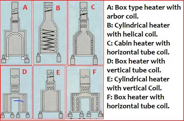
The disadvantage of vertical types of radiant tubes is their difficulty in replacement due to the smaller gap between the wall and the tube.
Horizontal-type radiant tubes are weldable outside the heater firebox due to more space available in return header bends and plugs.
Constructional Features of Fired Heaters
Fired Heater Casing:
The metal plate is used to enclose the fired heater. Normally, CS plates 6 mm thick are used as casing material. Casing design temperature Outside 82 deg. C, Radiant floor – 91 deg. C. Max. temperature, CS can withstand 440 degrees C, however, oxidation starts at 270 deg. C.
Failure of internal refractory lining causes overheating of underlying steel casing. This will be revealed by local hot spots.
To prevent further damage to the casing plate
- Apply air
- Apply steam
- In extreme cases put water
- Put an additional refractory lined casing plate over the hot spot area.
Radiant section of a fired heater:
The portion of the heater in which the heat is transferred to the tubes primarily by radiation is known as the radiant section.
Convection section:
The portion of the heater in which the heat is transferred to tubes primarily by convection.
Bridge wall:
The section separates the radiant & convection sections. The temperature of flue gas leaving the radiation section is called the bridge wall
Arch:
A flat or sloped portion of the heater radiant section opposite the floor.
Radiant Coils:
The radiant coils are located in the radiant section of the furnace where the heat picks from flame & high-temperature flue gas & hot refractory.
The radiant tubes may be either vertical or horizontal, depending on the construction of the furnace
Main Sections of a Fired Heater
Convection section:
Bank of coils which receive the heat from hot flue gases mainly by convection.
- Finned/studded tubes are often used in convection coils due to lower flue gas temperatures. Finned tubes ( 1.3 mm thick strip 200turn/meter) are difficult to clean when compared to studded (12.7 mm dia)
- The rate of heat absorption tends to be high at the entrance to the convection section in heaters, where the convection section is right above the radiant section. Tubes in this section are called shock/shield tubes. Normally, the first two rows absorb half of their heat in this section.
- Consists of a large tube support plate located in the convection section and supports. The material of end supports & intermediate supports is usually low-alloy steel.
- Replacing /Repairing of Convection tube support sheet is difficult & calls for the removal of all convection coils or it is necessary to lower the entire module.
- Tube support sheets are 25 cr-20 Ni or 50 cr -50 ni MOC.
Plug header:
A bend, provided with one or more openings for the purpose of inspection, initial measurement of coke before cleaning.
- Ensure proper depressurization before opening the plug.
- Ensure the Arrow mark is maintained on the plug to ensure the plug nut is guiding
- After the repair /replacement of the plug hydro test of the coil pass is recommended.
Fired Heater Internal Tube supports:
- Tube supports are metal devices that support the weight of the
- The tube guide is used to direct the movement of tubes in one particular direction.
- These are metallic members able to withstand high temperatures used to prevent the sagging/bowing/buckling/ swaying of tubes
- Tube supports are more prone to high-temperature oxidation and fuel ash corrosion.
- Horizontal roof tubes of box-type heaters are supported by means of hangers
- Tube supports must be aligned perfectly in one straight line.
- The use of fillers of any kind is prohibited.
- Ensure perfect contact between supports and tubes.
- Coils shall rest uniformly all over the supports.
- Failure of tube supports may take place due to mechanical overloading caused by the bowing of tubes, loss of strength of supports, and tube vibration.
- The tube support/hangers/guides shall be examined for cracks, oxidation, missing sections, and missing/broken or oxidized bolts.
Common problems associated with Fired Heater tubes
These are some common problems associated with fired heater tubes:
- Tubes are designed for approx 1 year life-1,00,000 hrs.
- Tube distortion – Hot spots, Sagging, Bowing, Touching of tubes.
- Tube surface – Pitting, Scale, Evidence of overheating.
- Observe & monitor the skin temperature, and compare the residual life of the tube.
Fired Heater Tube cleaning
- Generally, tubes are cleaned manually making scaffolding inside the heater.
- Ensure All burner tips are covered while cleaning.
- Ensure Fire bricks are covered to avoid ingress of foreign particles between the bricks to provide expansion of refractory during operation.
- Ensure no damage to refractory while making scaffolding.
Hydro-testing of the fired heater coils
- The hydro test is performed when the new coil is installed/repaired in the coil is
- Coils shall be hydrostatically tested, thoroughly drained after the test is completed and to be drained by blowing compressed air to avoid hammering &
- During the hydro test due to return bends & elevation differences adequate care is to be taken to vent air.
Stack
- Cylindrical steel is an insulated shell that carries flue gases to the atmosphere & provides the necessary draft. The stacks shall be externally inspected for hot spots and external corrosion. Check, if any unusual vibration of the stack exists.
Burners of a fired heater
- Burner: Introduces fuel & air into the heater at the desired velocities, turbulence, and concentration to establish and maintain proper ignition and combustion.
- Pilot: A smaller burner that provides ignition energy to light the main burner.
- Plenum or wind box: A chamber surrounding the burners that are used to distribute air to the burners or reduce the combustion noise.
What is a fired heater Draft?
A draft is the pressure differential that persists between air/fuel gas in the combustion chamber and atmospheric air. The draft is caused due to density difference between hot fuel gas and ambient air.
A negative draft must be maintained in every part of the fire heater so that hot fuel gas cannot be leaked out. Draft reading in the middle of the furnace is used to control the draft & excess air. A heater draft is required to pull out fuel gases from the heater.
How draft is generated?
The draft can be created by the following means,
- Full open the damper and close the louvers.
- Open purging/snuffing of steam
- Cut off the steam flow.
- A close damper as per draft requirement.
Draft Profile across the fired heater furnace
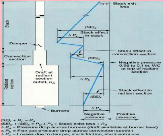
In the above image,
- (SE)r is the Stack effect in the radiant section
- (SE)c is the stack effect in the convection section &
- (SE)s is the stack effect in the stack
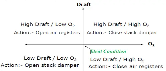
Draft & Excess air Control Scheme:
Draft and air are closely linked together & they should act together. The main objective should be achieving the optimum air level for the complete combustion of fuel.
Natural Draft fired heater:
In this type of heater fuel gas or air is injected into the heater by using atmospheric pressure & the combusted gas is vented out through the stack. No external means are used. This is happened due to density differences as hot gases are having a lower density than the normal atmospheric air.
Force Draft fire heater:
In this type of heater fuel gas or air is pushed into the heater by means of an external means like a fan. It is often called an FD fan, it provides air or fuel gas. The FD fan is installed before the furnace.
Induced Draft fire heater:
In this type, the fired-heater fan is installed above the heater so that it can induce air through the combustion chamber into the burner. This fan causes a negative draft which pushes the burnt air out through the ventilation system.
Advantages of using Force draft:
The forced draft system requires a lower level of excess oxygen. The flame becomes stable & small size of the burner is required. FD fan maintains an optimum ratio of air to fuel gas.
What is Bridge Wall Temperature?
It is the temperature of the flue gas which is generated due to the combustion of fuel gas at the radiant section and entered into the convection section. The rate of heat transfer at the convection section is governed by the bridge wall temperature. It should be in the range of 760-900ᵒC.
Why snuffing steam is used in fire heaters?
The main purpose of using snuffing steam is to snuff unwanted fire (that can cause due to tube leakage) by excluding air ingress or prevent potential fuel from air exposure as well as it carries away heat to some extent. The amount of snuffing can be based on the requirement of 8 lb/hr per cubic foot of furnace volume. Normally LP steam is used for this purpose. During the start-up of the heater operation snuffing steam is also used to remove combustible gas & excess air as well as create a negative draft.
What is Puffing?
It actually indicates a huge vibration of furnaces. If a burner is seriously out of fire, opening air control without reducing the firing rate can cause a hazardous situation called puffing. To prevent such a scenario first slow down the firing & then adjust the air louvers.
Start-up of fired heaters
- Make sure all the utilities are supplied as per requirement.
- Ensure every instrument & safety device are in operation.
- Ensure the fuel for the burner with sufficient operating pressure.
- Purge combustible gas inside the furnace by snuffing steam to cause a negative draft of -5 to -15 mm H2O in the radiant section. This is done by fully closing the louvers & opening the stack damper completely.
- Ignite the pilot burner and then the main burner.
- Check the concentration of O2 in flue gas and heater draft.
- The ramp of raising process fluid temperature at 30-50 C/hr to prevent overfiring.
- Once the furnace has been brought up to a steady state, then switch the control mode from Manual to Auto mode.
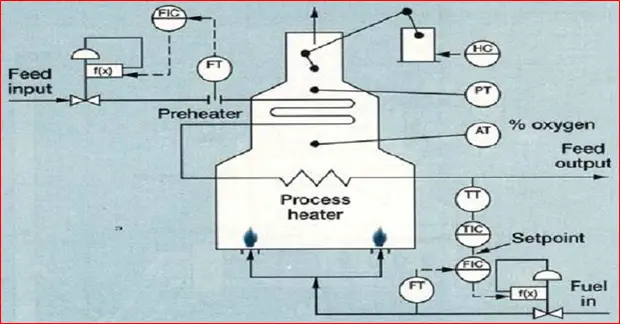
The control scheme of the fired heater
The following image shows a typical control scheme for fired heaters.
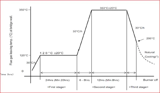
Heater Dry-Out
It is a very important operation of a fired heater prior start-up of a fired heater from a long shutdown or the start-up of a new fire heater. Heater dry-out is usually done to remove moisture contained in the refractories as refractories contain a large amount of moisture absorbed from the atmosphere. Ramp up of temperature is very crucial as a fast temperature increase may damage the refractory lining & surface shrinkage. Refer to the following figure that provides a Heating curve for heater dry-out.
Annual Maintenance
- Tubes visual inspection prior to cleaning
- Inspection after cleaning
- Dimensional check-up (OD of a tube), thickness.
- Visual inspection of header plug leaks
- Inspection – tubes supports, hangers, etc.
- Inspection burner assemblies
- Inspection of refractory
- Inspection of explosion doors
- Dampers external, internal, operating linkages, etc.
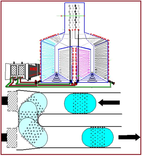
Decoking by Pigging
Due to exposure to high temperatures inside the fire heater coke is deposited in the tube which may lead to a reduction of heat transfer & the tube can be choked. So decking is a necessary operation that is performed by using the variable size of pigs, chemical & combustion methods. Mostly pig decoking is preferred over another. A pig has a uniformly studded pin around its surface which helps removals of carbon depositions inside the tube walls.
- A new method of decoking the tubes is to steam, and then use water pressure to push Styrofoam pigs with studs and grit on the exterior through the tubes and around u-bends (even u-bends with clean-out plugs). The pigs scrape out the coke without scratching the tube walls.
- The improper size of the pig may leave scratches on the tube walls, hence a selection of the correct size of the pig is
- Pigging is faster than steam-air decking, and refiners generally have longer campaigns on the heater compared to steam air decoking.
- Pigging will not provide temperature shocks & hence pigging has been found effective.
PIGGING – Double Pumping Unit
Set up:
- The connection is made to a pair of passes (coils) with flow/return piping. There are four separate piping links with the furnace & pumping unit.
- Launchers/receiver units complete with full port ball valves to be connected to Coils horizontally.
- Ensure safe access to pig launchers/receivers.
- Launchers/receivers are provided with hammerlock couplings to connect flexible piping.
Cleaning of Pigging:
These are some procedures for the cleaning of Pigging:
- Water fill-up.
- Water circulation for removing hydrocarbons and loose debris.
- Special density foam pig launch
- Decoke pig selection to clean
- Increase pig size incrementally.
- Polishing by using oversize abrasive-coated foam pig.
Air-to-Fuel Ratio
It is an important factor to maintain in fire heater operation. Basically, it is the mass ratio of air to fuel present in the combustion process. For controlling air pollution to meet the regulatory norms it is an important parameter to measure & maintain. Under ideal conditions, fuel mixes with air to perform complete combustion. At the end of the combustion no excess oxygen & unburned fuels are left in the combustion chamber, it is called stoichiometric combustion. But in the real scenario, some amount of excess air should be present to ensure complete combustion of the fuel. Otherwise, significant amounts of CO are produced, reducing efficiency & increasing pollution levels.
Effects of excess fuels result in loss of fuel, CO production & caused heavy smoke while effects of excess air result in a reduction of temperature & excessive heat losses.
Troubleshooting of Fired Heaters
| Problem | Reason | Recommendation |
| High flue gas temperature | Fouling in convection section Burnt off fire Over-firing | Clean convection section Replace convection tubes Reduce firing |
| High Fuel gas pressure | Burners are plugged | Clean burners |
| High-pressure drop in tubes | Coke formation High rate of vaporization | Decoking of tubes Reduces the flow rate |
| Excess air | High furnace draft Poor air-fuel mixing Air leakage in the furnace | Reduce furnace draft Modify burners Plug air leakage |
| Flame flashback | Low gas pressure | Raise fuel gas pressure |
| Burners go out | The gas mixture is too dilute | Reduce air. |
| Insufficient heat release | Low gas flow rate | Increase gas pressure |
Some more resources for you!
Piping Design and Layout
Piping Stress Analysis
Piping Interface
Piping Material
Piping Design Software
Thank you, this is a great introductory post!
I just wanted to add that the heaters shown in the photo graphs are typically designed in accordance with API 560 Standards. There is a new fired heater simulation software called Heater560, which is specifically for API 560 Heaters and is now available for process engineers interested in Fired Heater Design
I want hydro decoking of my LRV heater coil. Want to buy equipments and technical assistance.
I really appreciate your efforts. You have shared a valuable blog post. Keep sharing!!
Thank you so much sir.
It’s very useful.💐💐
Is the tube/coil design as per pressure vessel or piping code?
Dear Anup ji , Really very useful and good for us. We are suppliers of Heater tubes/Bends to many heater manufacturers . So far we have come across Grade P11/P22/P5/P9/SS Grades like 304H/321/347/347H and some time 600/800 grades . Can you share if you have more idea on materials ? Our interest is to learn more and more on materials .
Kind regards
Can I get your contact details ?
Need tubes
Very informative. What is the optimal 02 level for combustion? Is that based on what you are burning? We primarily use natural gas, but also burn our off gas. We are a used motor oil refinery. Our products are asphault and VGO.
very informative
great Blog
valuable information, thank you.
as a fresher in the oil and gas industry . this articles aptly gives us a summary sir . thank you very much sir.
Hello Anup,
People are developing natrual gas crackig technologies to produce hydrogen and carbon. Please check the companies, Hazer, Hycamite, Graphitic Energy, etc., to see for them how to heat their reactors to >800-1000C at commercial plant scale, beyond pilot test? An example is SMR, giant furnace over 10 meters tall with hundreds of Inconel tuber reactor.
Thanks