
Jacketed piping is a specialized engineering solution used in various industries to transport fluids that require precise temperature control, such as chemicals, food products, and pharmaceuticals. This complex system combines two distinct pipes: an inner or core pipe that carries the process fluid and an outer or jacket pipe that contains a separate heating or cooling medium. Jacketed piping systems are designed to maintain the desired temperature of the process fluid throughout its journey, ensuring product quality and process efficiency. In this comprehensive guide, we will delve deep into every aspect of jacketed piping systems, covering their components, design considerations, applications, advantages, and challenges.
What is a jacketed Piping?
Jacketed piping is required to transport highly viscous fluids having very low flowability. The jackets usually provide temperature to the core pipe so that the flowability of the fluid inside the core is maintained. The jacketed piping system consists of two pipes of different sizes. The larger pipe covers or jackets the smaller size pipe. Jacketed piping is often referred to as jacketed pipe or jacketed tubing.
Components of Jacketed Piping
Jacketed piping consists of four main components. They are:
- Core Pipe: This central smaller-sized pipe of a jacketed piping system that carries the fluid from one point to the other.
- Jacket Pipe: This is the larger size pipe that carries superheated steam to maintain the temperature of fluid flowing in the core pipe.
- Steam Feeder: This is a tapping connection in the Jacket pipe to provide a path for the steam inlet or outlet.
- Spacer/ Guide Plate/ Spider: Spacers shall be provided for supporting the core pipe from the jacket pipe and to ensure a uniform gap between the core and jacket pipes. The detailed dimensions and design of the spacer shall be as the design guide of jacketed piping prepared by the layout team. Stress engineer to follow spider spacing chart while analysis.
Types Of Jacketed Piping
Depending on the nature of the jacket pipe over the core pipe, two types of Jacketed Piping are found; Continuous jacketing and Discontinuous jacketing.
Continuous Jacketing: In this type of piping all piping components including the straight lengths of pipe, fittings, flanges, valves, and branch connections are fully covered by the jacketed pipe.
Discontinuous Jacketing: This type of Jacket pipe consists of jacketing of only straight lengths of the core pipe. Here Branch connections, elbows, Tees, other Fittings, and Valves are not jacketed.
Applications Of Jacketed Piping
Jacketed piping is not used widely and has got some limited applications. This type of piping is only required where a certain temperature needs to be maintained throughout the transportation of fluid from one point to another. Some of the typical examples of jacketed piping are:
- To transport molten Sulphur through pipes in a sulphuric acid plant.
- To convey cryogenic liquid oxygen in the oxygen generation unit.
- Jacket piping can also be used to stop the piping network from getting frost.
- To maintain fluidity throughout the piping network in the vegetable oil manufacturing plant
- To keep the pipeline system warm when passing through cold areas.
- To stop choking of pipes because of extremely cold temperatures in a Bulk career merchant ship.
Design Consideration for Jacketed Piping Systems
Jacketed piping systems are highly complex systems as compared to the usual process piping due to their double-walled piping network. So, these types of piping networks require special consideration during the engineering, designing, and execution phase. Some of the design points are mentioned below:
Fluid Pressure: The core pipe will be subjected to both internal and external pressure. So the thickness of core piping must be designed for both pressure considerations. Also, It is preferable that the fluid flowing in the core pipe has lower operating pressure as compared to the jacket pipe. This will ensure that the product can be contained in the jacket for any unforeseen failure in process core piping.
Feeder Port Location: The feeder inlet and outlet port locations vary as per the media in the jacket pipe. For Liquid medium in the jacket pipe, the inlet feeder port should be located at the lowest point and the outlet should be at the highest point. This will ensure the jacket is filled with media before leaving the system.
While for gaseous media in the jacket, the Inlet port of the feeder should be at the highest point and the outlet point should be at the lowest point.
Slope: A jacketed piping system is usually installed with some piping slope to help in the fluid flow of the core pipe. This will also ensure the complete drain out of process fluid from the core pipe.
Fluid Flow Direction: The fluid flow direction inside the core and jacket pipe preferably be opposite to each other for better heat transfer. This will increase the heat transfer efficiency.
Continuity Breaks And Joints: The number of break-up flanges should be minimized to reduce fitting costs.
System Components And Layout: During the designing of the jacketed piping network following points need to be considered:
- Thermal difference and expansion between the core pipe material and jacket pipe material.
- The potential of corrosion on both the core and jacket side of the pipe.
- Types of section connectors to be used.
- Any requirement of turbulence mechanisms in the pipe such as flow disruptors, fins, and wraps.
- Internal supports or guide strips are installed between the jacket and core pipe.
Here are some additional general guidelines for jacketed piping design:
- Determine the Process Requirements: Determine the temperature range and the heating or cooling medium required for the process fluid. This will determine the size and type of jacket required.
- Select the Appropriate Materials: Select materials for the inner and outer piping and the jacket that are compatible with the process fluid and the heating/cooling medium. The materials should also be able to handle the required pressure and temperature range.
- Determine the Jacket Type: Choose the appropriate type of jacket for the application, such as a half-pipe jacket or a dimpled jacket. The jacket should provide sufficient heat transfer to maintain the desired process temperature.
- Calculate the Heat Transfer Area: Calculate the heat transfer area required to maintain the process fluid temperature. This will depend on the temperature range, fluid flow rate, and the heat transfer coefficient of the jacket.
- Determine the Jacket Width: The width of the jacket should be determined based on the heat transfer area and the size of the inner pipe. The jacket width should be sufficient to provide adequate heat transfer while maintaining a reasonable flow velocity.
- Design the Connections: Design the connections between the jacketed piping and other components, such as pumps or vessels. The connections should be designed to minimize stress and prevent leakage. Flanges, threaded connections, or welded connections can be used depending on the application.
- Insulation: Choose an appropriate insulation material and thickness based on the temperature range and the application. The insulation should be sufficient to minimize heat transfer between the jacket and the environment.
- Consider Expansion and Contraction: Consider the thermal expansion and contraction of the piping system due to changes in temperature. Adequate space should be provided to accommodate these changes and prevent stress on the piping system.
- Testing: Test the jacketed piping system to ensure that it meets the required specifications and is functioning properly. Tests may include hydrostatic testing, pneumatic testing, or other non-destructive testing methods.
It’s important to note that specific design guidelines for jacketed piping may vary depending on the application and industry standards. Therefore, it’s essential to consult with experts in the field to ensure that the design meets the specific needs of the application.
Introduction to Jacketed Piping Stress Analysis
Jacketed piping requires special stress analysis. Jacketed piping is commonly used to convey very viscous process fluids in an inner pipe, heated by steam/hot water/hot oil or other heating media between the jacket and core pipe. Fig 1 shows the normal components of a jacketed piping system. General Definitions of Jacketed Piping Components for stress analysis are mentioned below:
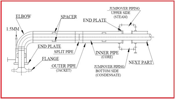
Partition Plate/End Plate:
A partition plate or end plate shall be placed where the flow of steam or heating medium is interrupted for fully jacketed system or at the end of the partially jacketed system. The detailed dimensions and designs shall be as a design guide prepared by the layout team for jacketed piping.
End Closure:
End closure shall be used to terminate jacket piping. There are two types of end closure: Cap Type and Plate Type.
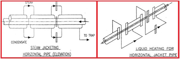
Jump-over:
The length of a single jacket circuit is limited & the supply of heating medium cannot be provided separately for each circuit. Jump-overs (Fig. 2) are used to connect two different jacket circuits in series for a continuous supply of heating medium and draining system. Details of Jump-over sizes and design shall be as per the guide prepared by the layout team for jacketed piping.
Jacket Medium:
The heating medium can be gas or liquid.
Reinforcing Ring Plate:
In case the jacket pipe is to be terminated on the core pipe having a thickness of SCH 10S and below, the core pipe shall be suitably reinforced with a reinforcement ring at the weld joint.
Supporting Concept for Jacketed Piping Systems
All supports shall be provided on the jacket pipe.
CAESAR II Modelling of Jacketed Piping
Modeling the Core Pipe:
The core pipe of a jacketed piping system is modeled in Caesar II as per the below-mentioned steps
- Do not give pipe insulation thickness while modeling core pipe.
- The temperature should be the temperature of the process line.
- Pressure should be the pressure of the process line.
- Fluid density should be the fluid density of the process fluid.
- No wind/wave or earthquake is to be applied on the core.
- All core bends are of large diameter (R = 1.5D). For slurry lines where the radius may be 4D then the same shall be entered (refer to project standard).
- In the case of Cross-Arrangement for providing a rodding facility, SIF can be obtained from the vendor and shall be entered in all four points of Cross-Connection.
- No supports shall come directly on the core pipe.
- The selection of node numbers is the same as normal pipe modeling starting from node 10.
- All spiders, which are acting as internal supports, can be modeled as vertical restraints plus lateral restraints (guides) with gaps as mentioned in the jacketed piping specification.
- The location of the spider shall be presumed before modeling & provide a free node at that location.
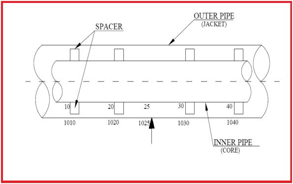
- At places where the jacket will be supported, give node numbers of those locations in the core pipe like 5, 15, 115 (Refer to Fig. 3), etc. All other nodes will be multiple of 10.
- The starting and finishing node to the rigid node should be defined as restraints, which will help to connect the core pipe and jacket pipe.
- All rigid elements shall be modeled as a normal modeling procedure.
Modeling the Jacket Pipe:
The following steps are used to model the jacket pipe:
- An easy way is to model the jacket pipe by running through the entire core and then duplicate the core piping using a proper node increment (like 1000).
- Change the diameter of the jacket pipe according to the specifications.
- Change the wall thickness of the jacket pipe.
- All jacketed bends are of short radius i.e. R=1D. For slurry lines, the radius may change. Refer to project standard.
- In the case of Cross-Arrangement for providing a rodding facility, SIF can be obtained from the vendor and shall be entered in all four points of Cross-Connection.
- Apply insulation thickness and insulation density.
- Apply wind/wave/seismic if any.
- The temperature should be the temperature of the heating medium.
- Pressure should be the pressure of the heating medium.
- All supports should be on the jacketed portion only.
- If steam is flowing in the jacket pipe then put the density as zero, otherwise, follow the formula provided in the next point.
- If both the jacket and the core are fluid-filled, the fluid density of the jacket must be reduced to avoid excess (incorrect) weight. Caesar-II does not do this automatically.
- Calculate the actual density as per below calculation:-
- Actual jacket fluid density = [(rj2 – Rc2)/ rj2 ] x dj
Where, rj = Inner radius of the jacket; Rc = Outer radius of the core; dj = Density of heating medium
Combining the Core and Jacket Modeling:
- The jacket will end with flange joints/ Plate/ Capped End. So at these points, there will be a physical connection between the core and the jacket. So these points need to be connected by an anchor. For example, if there is a flange at node 50 then;
50 ANC CNODE 1050; 60 ANC CNODE 1060
Delete the rigid element 1050-1060 from the jacket portion.
- At the spider locations, define Y, and Z restraints (on the core pipe) if the pipe is in the X direction and then connect it by giving CNODE on the jacket.
- If the line is partially jacketed then model it the same as the full jacket piping and delete the element from the jacket portion where the line is not jacketed.
- Somewhere in the full jacketed system delete the rigid element.
- In some systems, the jacket and the core consist of different materials. This condition must be modeled very carefully since the thermal growth in the core will be different from the thermal growth of the jacket.
Analysis and Other Calculations
Some points to take special attention
- In general engineering practice, the maximum length of the jacket served by one hot water inlet shall be 20m and one steam inlet shall be 25m.
- In the same way, the total length of one circuit shall not exceed 20m in case of continuous jacketing and 25m in case of discontinuous jacketing.
- Max length required for a single jacket shall also be dependent on the buckling load (Pcr) check.
- Jump-overs shall be designed such that air pockets may be avoided with a heating medium as the liquid.
- The flow of the heating medium through the jacket shall be in series to avoid any cold points in the system.
- For heating medium, as liquid, the feed and drain nozzle shall be provided at the lowest and highest point of the jacket respectively. For heating medium, as vapor, the feed and drain nozzle shall be provided at the highest and lowest point of the jacket respectively.
- As far as possible flange joints on the core pipe shall be avoided. They are to be provided only at equipment nozzles, valves, sp. fittings, instruments, etc. having flanged ends. Also for lines that need to be dismantled during maintenance.
- Additional lateral restraints, in the form of spacers, can cause high axial loads which could conceivably initiate distress at the pipe to flange welds.
- Spacers should be located to act only as ‘supports’ for the deadweight bending of the core pipe. The indiscriminate location of spacers can produce a “locked-up” condition resulting in high expansion stresses. Check forces on Spiders. The forces shall not be too high that cause bending/ crushing of spiders. Spider is meant just for alignment.
- Sometimes break-up flanges may be required after each change in direction. Stress engineer to model the same from initial modeling. And sometimes in a straight run, two/three break-up flanges may come. In that case, the force and moment at anchor points will be too high if the temperature differential between the core and jacket is large.
- The weight of flanges and valves used for jacketed piping and flanges will be reduced flanges and valves may be jacket valves. Weight shall be taken from vendor print.
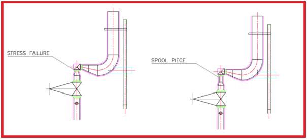
- After each jacketed reducer provide at least a 300 mm spool piece (Refer to Fig. 4) before attaching any flange or reducer to reduce chances of thermal failure if required. Inform the layout about this from the initial stage to avoid unnecessary changes later. (For control valve assembly and PSV lines)
Specifying a Jacketed Piping
Jacketed piping is a type of piping used in applications where the process fluid needs to be maintained at a specific temperature. The jacket is typically an outer shell that surrounds the inner piping, which is used to circulate a heating or cooling medium. Here are some general specifications for jacketed piping:
- Materials: The materials used for the inner and outer piping and the jacket depend on the process conditions and the fluid being transported. Typically, carbon steel, stainless steel, or other alloys are used.
- Pressure Rating: The pressure rating of the jacketed piping should be equal to or greater than the pressure rating of the process piping. This ensures that the system can handle the pressure of the process fluid.
- Insulation: The jacketed piping should be insulated to minimize heat transfer between the jacket and the environment. The insulation material should be chosen based on the temperature range and the application.
- Welding: Welding of jacketed piping should be done in accordance with the relevant industry standards, such as ASME B31.3 or B31.1. The welds should be tested and verified to ensure the integrity of the system.
- Connections: Connections between the jacketed piping and other components, such as pumps or vessels, should be designed to minimize stress and prevent leakage. Flanges, threaded connections, or welded connections can be used depending on the application.
- Testing: The jacketed piping system should be tested to ensure that it meets the specifications and is functioning properly. Tests may include hydrostatic testing, pneumatic testing, or other non-destructive testing methods.
- Quality Control: The manufacturing and installation of jacketed piping should be done with strict quality control measures to ensure that the final product meets the specifications and is safe for use in the intended application.
It’s important to note that specific jacketed piping specifications may vary depending on the application and industry standards. Therefore, it’s essential to consult with experts in the field to ensure that the design and installation meet the specific needs of the application.
Jacketed Piping Fabrication Procedure
The fabrication procedure for jacketed piping typically involves the following steps:
- Material Selection: Select the appropriate materials for the inner and outer piping and the jacket. The materials should be compatible with the process fluid and the heating/cooling medium. The selection should consider factors such as temperature, pressure, corrosion resistance, and cost.
- Cutting and Shaping: Cut the inner and outer piping to the required lengths and shapes using cutting tools such as saws or torches. Ensure that the cutting is done accurately to achieve a tight fit between the inner and outer piping.
- Welding: Join the inner and outer piping using welding techniques such as TIG, MIG, or stick welding. The welding should be done in accordance with industry standards and the appropriate welding procedure specifications (WPS).
- Jacketing: Wrap the outer piping with the jacket material, ensuring that there is sufficient space between the inner and outer piping for the heating/cooling medium to flow. Secure the jacket material to the outer piping using welding or clamping.
- Insulation: Apply insulation material around the jacketed piping to minimize heat transfer between the jacket and the environment. The insulation material should be selected based on the temperature range and the application.
- Pressure Testing: Test the jacketed piping system to ensure that it can handle the process pressure without leaks or failure. The test should be done in accordance with industry standards and applicable codes.
- Quality Control: Perform quality control checks throughout the fabrication process to ensure that the final product meets the required specifications and standards.
It’s essential to follow the appropriate fabrication procedure and industry standards to ensure that the jacketed piping system is safe and efficient. Additionally, it’s important to consult with experts in the field to address any specific concerns or requirements for the application.
Sir I want to ask you a modelling approach for jacket pipe at termination point of connecting equipment.
1.Can we anchor core or jacket pipe(Any one) and connect both by using C-Node?
2.Mention two different anchors in both core and jacket and mention c node in any one of them?
3.mention 2 different anchors of both core and jacket and one more anchor with c-node mentioned?
Please clarify.
Hi anup i am amir from iran
I am a piping engineer too i need to your advice about a working problem please say to me about a way to connection
My phone number: +989210103986
Email:amirsaber987@gmail.com
Now I know a jacketed piping system is used when you are working with thicker fluids. If I am an engineer, I would understand how fluid flow simulation is useful in this regard to predict how these systems could work and analyze calibrations to make them more efficient. These technologies are really changing process engineering.
There won’t be end caps before flange connection in jacketed piping, instead, there will be a special flange where inner pipe is butt welded and outer pipe will be flare type weld, and mostly outer pipe fittings will be splitted type.
Hello Anup ,
From last few days the content PDF is not getting downloaded , could you please help in it.