
The local primary membrane stress (PL) is the stress generated due to a primary type load such as weight or pressure, but that is localized around a discontinuity such as a nozzle in a vessel.
According to ASME sec VIII div-2 part 5, A region of stress in a component is considered local if the distance over which the equivalent stress exceeds 1.1S does not extend in the meridional direction more than (Rt)0.5 where R and t are radius and thickness respectively.
Sometimes we face a big challenge to deal with these local stresses. Although they are very local, they are more than allowable. In these cases, the use of the elastic-plastic method instead of elastic analysis may help us to get rid of such stress categorizations.
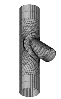
Let’s take a look at the below example to elaborate more. As you can see there is a simple unreinforced lateral connection with a header of 1524mm OD and 16.05mm as the thickness. The OD of the branch is 1219.2 mm with a thickness of 9.7mm.

A 0.36 MPa Internal Pressure is the only load that would be applied to this connection and it is assumed that the working temperature is 3100 C with allowable stress of 119 MPa. The material is assumed A106-B.
Shell elements and elastic methods have been used to perform FE analysis for this connection. The below figure shows the applied load and Boundary conditions.
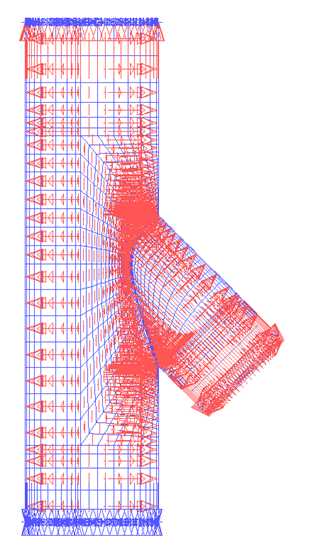
Two Fixed BCs have been applied to both sides of the header. The internal pressure load has been shown with red arrows. In the below figure, the contour of PL has been shown.
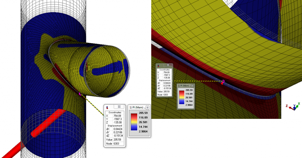
The maximum PL stress is about 205 MPa and has been located on the branch side next to the header weld, as it is expected.
The below figure reveals how local the highest stresses are. However, they have exceeded the allowable which is 1.5S or 179 MPa.
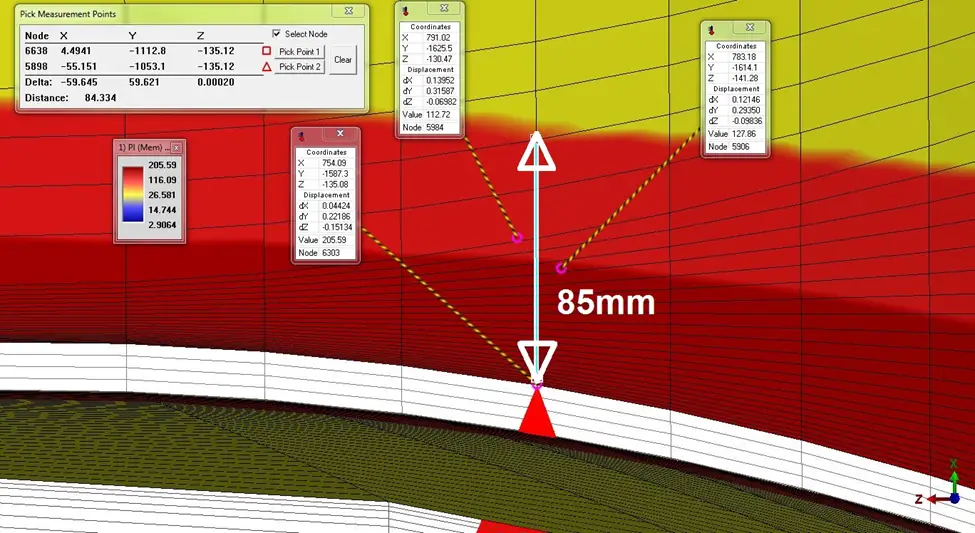
As you can see the extent of the highest stress zone that exceeds 1.1S (131 MPa) is much lower than (Rt)0.5 of the branch.
It seems that a reinforcement pad will solve this problem. To investigate how it works, a new geometry that is the same as the previous one and also includes a reinforcement pad has been analyzed. The width and thickness of the pad are 500 mm and 16.05 mm respectively.
Now you can see the results. The maximum PL stress has changed to 153 MPa.
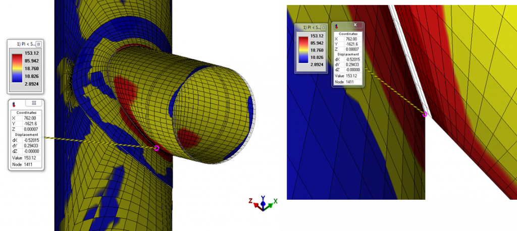
Therefore, when a reinforcement pad is used the PL stress will be in the allowed range.
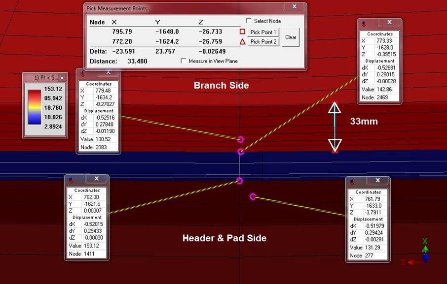
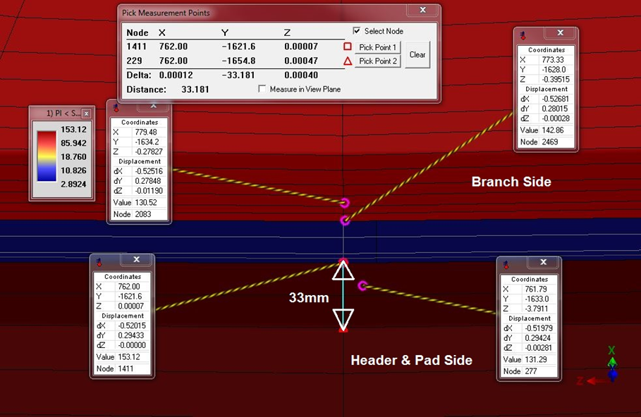
Also, the below figures show the extent of the highest PL stresses that is obviously much lower than (Rt)0.5 on both branch and header sides.
Another way to investigate this connection is the method that has been mentioned in para. 304.3.3 of the B31.3 code is about the reinforcement of welded branch connections. Following the mentioned rules reveals that using a pad reinforcement is not needed. Indeed, the basis for pressure design in this paragraph is to ensure excess area at discontinuity to account for material removed from the nozzle internally. This method does not attempt to discern stress at the discontinuity as well as some plasticity that may occur at design pressure.
But now the question is how we can justify this discrepancy between elastic FEA and the method mentioned in para. 304.3.3 of B31.3.
In the last step, an elastic-plastic method is used to study this connection without a reinforcement pad again. Diving into plastic analysis is not the intent of this short article. However, some of the assumptions are as follows.
The ASME sec VIII-2 part 3 multilinear stress-strain curve has been used. The material type is Ferritic steel while the amount of yield stress and tensile strength at working temperature is 177 MPa and 413.7 MPa respectively.
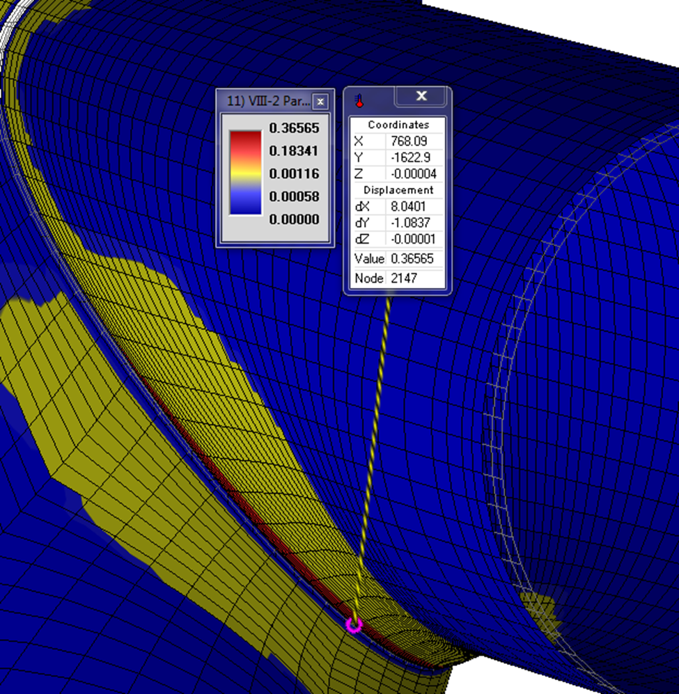
Since the convergence is achieved, there will be no collapse failure. Also, the amount of the highest plastic strain is about 0.08 and as it is expected has been located on the branch side. The below figure shows that the highest plastic strains are very local.
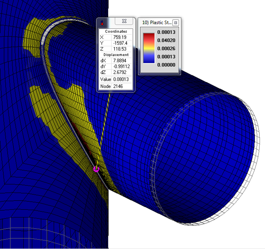
The local strain limit criteria (ASME VIII-2) have been also passed and the maximum ratio of plastic strain over limiting triaxial strain ɛpeq/ɛL is about 0.36 which is lower than 1.
Finally, it is concluded that the connection is qualified using elastic-plastic analysis and no reinforcing pad is needed.
Indeed, with the help of a more advanced method, we were able to optimize the design and make sure that the plastic strains are local enough to qualify an unreinforced connection even for such a pressure load.
I would like add few more point to this article.
1. If the failure is away from SQRT(Rt) from the discontinuity, then it is better to increase header or nozzle thickness where there is overstress.
This will happen when the junction is highly rigid and the nozzle or header is highly flexibile.
2. ASME Sec VIII protecting the vessel or pipe from various modes of failure. Elastic-plastic approach in the article holds good for “Protection against Plastic collapse” criteria. At the same time, care should be taken if the same pressure load is cyclic. Plastic strain will significantly reduce the allowable number of cycles in the “Protection against cyclic loads” criteria.
Baskar,
I agree. Cyclic failure mode must be considered if there are any cyclic loads.
However, in this post only the pressure capacity of the connection has been discussed