
We all see pumps day in and day out. We see them in our houses, roadsides, industries etc. They are extensively used in adverse applications to transport fluids from one place to another.
What is a pump?
A pump is a mechanical device that moves fluids, solid wastes, chemicals, and slurries by mechanical action. The pump has two important components i.e. Flow & Head.
- Flow: It determines the amount of fluid pumped.
- Head: It tells the extent or distance to which fluid is to be exported.
There are two types of Pumps based on their operating principle.
- Dynamic pumps: They are further classified as Centrifugal Pumps, Vertical centrifugal, Submersible pumps, etc.
- Displacement pumps: They are further classified as Gear pumps, Piston pumps, Lobe pumps, etc.
As the pump works 24*7 in adverse environmental conditions, it has to be designed properly. Starting from NPSH(A) calculation to pipeline sizing calculation everything should be perfect. In this article, we will learn about “Pump Suction Intake Design Calculation.” The pump suction is designed as per the HIS (Hydrological Institute Standard). So, let’s see what the different terms are associated with pump suction design & how they are calculated.
Terms Associated with Pump Suction Intake Design
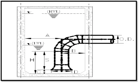
Bell Mouth
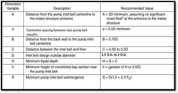
It is a piping structure that guides the intake of fluid to the pump. Bell Mouth width is given by D. Width of the bell mouth is calculated as 1.5 to 2 O.D. of the suction pipe.
End Wall Clearance (B)
It is the Clearance between the centreline of the pump suction intake bell and the end wall of the tank. It is calculated as 0.75D.
Centreline Spacing (a)
Centreline spacing between two adjacent pump bell mouths in the same tank will be calculated as 2.5D. This 2.5D is the minimum value.
Bell Mouth Floor Clearance (C)
It is the minimum gap that should be maintained between the bell mouth bottom and the top of the tank floor. It is calculated as 0.3D to 0.5D.
Minimum Submergence (S)
It is the minimum submergence of the pump bell inlet in water. This is calculated as D (1.0 + 2.3FD). Where FD stands for Froude’s number.
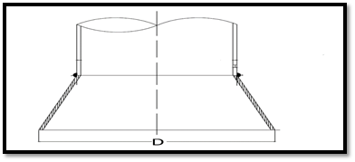
Minimum tank width (A)
This is the minimum distance between the pump bell centreline and the next pump wall. It is given by 5D.
Minimum Liquid Depth (H)
It is the minimum liquid depth required in the tank. This is given by the submission of Minimum submergence(S) + Bell Mouth Floor clearance(C). The lowest water level intake is calculated by minimum liquid depth.
The angle of floor slope (α)
This is the slope of the floor required in the tank. Generally, the floor is sloped so that an adequate amount of water is always available near the pump suction.
Impacts of Improper Design
- Cavitation
- Pump Dry Run
- Improper process parameters
- Improper calculation of NPSH(Available)
- Increase in OPEX.
- Vibration in pump body & suction piping
- Pump Head Loss
The pump suction should be designed considering the above-mentioned parameters. If the suction of the pump is not designed properly there may be problems like cavitation, pump dry run, the problem of priming, etc. So, if you don’t want that these problems to be part of your real life & you want your OPEX to be the least these design considerations should be followed carefully while a pump system is being designed.
Typical Calculation of Pump Suction Intake Design
Consider a pump of flow Q = 1640m3/hr.
- Pump suction bell design (D) = 1.5* O.D. of pipe
To Calculate the Diameter of the Pipe: Q = A.V.
Where
- A = Cross-section area of Pipe or (A=π/4 * D2)
- V= Velocity in pump suction side (velocity in the suction pipe is generally considered in the range from 06 to 1.5m/s.
Minimum submergence (S): S = D (1+2.3Fd)
Where
- Fd = Froudes Number (It is a dimensionless number)
- FD = V/(gD)^0.5
- V = Velocity in m/s
- D= Suction bell diameter
- g = Gravitational acceleration i.e. 9.81 m/s^2
Minimum sump clearance (C)= 0.3 to 0.5D
Lowest water level (H) = S+C
The gap from the centre of the wall to the pipe centre (B)= (0.3D to 0.75D)
| Flow(m3/hr | Inside Diameter(m) | Outside diameter(mm) | Bell design D) (mm) | Velocity(V)(m/s) | Froudes Number (FD) | Minimum submergence(S) (mm) | Minimum sump clearance (C) (mm) | Lowest Water level (H) (mm) | Gap of pipe from the centre wall (B) (mm) |
| 1640 | 0.695 | 711 | 1066.5 | 1.20 | 0.371 | 1978 | 320 | 2297 | 1386 |
Tutorial Video for Pump Suction Intake Design
For more clarification watch the below-attached video & subscribe to our channel
Few more Useful Resources for you.
Other Pump Related Articles
Piping Design and Layout Basics Related Articles
Piping Stress Analysis Related Articles
Piping Material Basics
Articles Related to Process Design Basics
Articles related to Civil Design Basics
Articles Related to Mechanical Design Basics
Articles Related to Instrumentation Design Basics
Calculation time & pressure for hydrotest.
Thank you, Anup
It is important to know the maximum suction depth to prevent solids from entering the pipeline. I need to find suction depth for the vertical suction pipe.
May be this topic is related with flow pattern line around suction pipe.
Do you know any literature about that ?
Thank you in advance
Dear, flow pattern as well as solids behavior are key points of analysis to prevent any particle entrainment towards the suction mouth. Please start by analyzing your tank as a sedimentation tank where solids are allowed to settle out far from of the liquid stream
I have a 12″ PVC line 2300 feet long that I want to use as a suction pipe.
This is a horizontal pipe in the river with 5 foot of head.
How much can I pull out of the pipe to fill a tank 15 feet tall?
Thank you,
Gregg
What’s the size of your tank? Do you have altitude above sea level and operational temperature chart for your pump?
Would you please cite the reference source(s) for the content presented in this article? Thank you.
Shouldn’t the Froude Number calculation be based on the equivalent diameter of the opening between the bell and the floor? For a 13.7″ bell diameter 4″ above the floor, the area of flow at entry to the bell is 169.6 in2 – equivalent to a 10.8″ circular inlet. Thus, the Froude number depends on bell-to-floor clearance.
If that clearance is not considered, there will be the risk of vortex at low submergence.
Hello couldn’t calculate this. Could you pls help me
What diameter is required for the inlet pipe for a 1,000,000-gallon (per 24 hours) capacity pump for a flow through the pipe of 15 cm per minute?
Good Sumerisation of Fire Pump designing and its installation.. All the very best.