
Radiographic testing (RT) is a non-destructive testing (NDT) method widely used to assess the integrity of materials and structures without causing damage. This technique plays a critical role in industries such as welding, aerospace, automotive, manufacturing, pipelines, and construction, ensuring safety and quality through precise evaluations. In this article, we’ll explore the principles, types, advantages, applications, and safety considerations of radiographic testing.
1. What is the Radiographic Testing?
Radiographic testing, or radiographic examination, is a non-destructive testing (NDT) method for examining the internal structure of any component to identify its integrity. Radiographic Testing or RT uses x-rays and gamma-rays to produce a radiograph of the test specimen that shows changes in thickness, defects or flaws, and assembly details to ensure optimum quality. Radiographic testing of welds to ensure weld quality is a widely used industry practice. Radiographic testing in welding is a highly dependable way to detect weld defects like cracks, porosity, inclusions, voids, lack of fusion, etc. in weld interiors. Because of its high dependability, radiographic testing is widely used in the oil & gas, aerospace, transport, military, automotive, manufacturing, offshore, petrochemical, marine, and power generation industries.
2. Radiographic Testing Principle
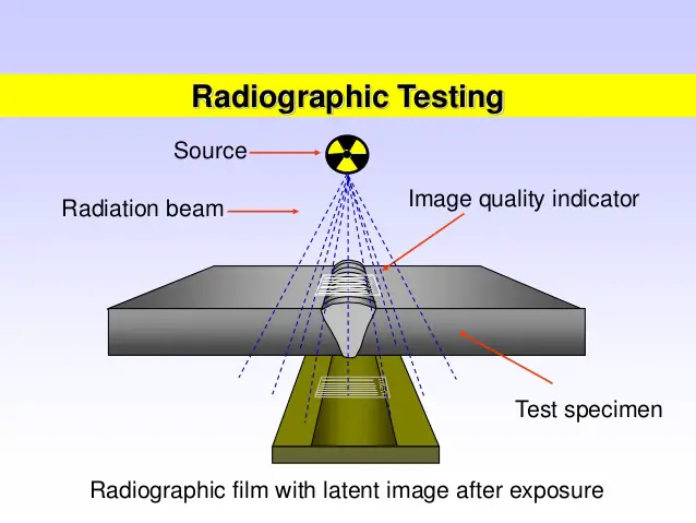
In Radiography Testing, the part to be tested is placed between the radiation source and a piece of sensitive film or detector. Once the x-ray or gamma-ray radiation is started, the test part will hinder some of the radiation by its material density and thickness. Thicker and denser material will allow less radiation to pass through the specimen. The film (or an electronic device) records the amount of radiation (known as a radiograph) that reaches the film through the test specimen. By studying the radiograph data, defects can easily be recognized. If the material is sound without any defect, entire rays will evenly pass through the material. But for materials containing flaws, rays passing through the flaws will get absorbed to a small extent due to the change in density.
Defects in parent metal reduce its density and hence they transmit radiation much better than the sound metal. Hence the radiograph film appears to be darker in the area exposed by the defects.
The penetration power of rays is dependent on the energy of the radiation. Radiation with higher energy can penetrate thicker and denser materials. As high-energy x-rays and gamma-rays are highly radioactive, local rules must be strictly followed.
In radiographic testing, defects are detected using thickness variation. So, the larger the variation, the easier the defect is to detect. But when the path of rays is not parallel to a crack, the thickness variation is less, and thus the crack may not be visible. That’s why it is always suggested to perform radiographic testing by sending rays at various angles.
In industrial radiography, various imaging techniques are employed to display the final results. These include:
- Film Radiography
- Real-Time Radiography (RTR)
- Computed Tomography (CT)
- Digital Radiography (DR)
- Computed Radiography (CR)
Each of these methods offers distinct advantages, catering to different inspection needs and preferences.
Industrial radiography utilizes two primary radioactive sources: X-rays and Gamma rays. Both types use high-energy, short-wavelength versions of electromagnetic waves, allowing for effective penetration of materials. Due to the inherent risks associated with radioactive materials, strict adherence to local safety regulations is crucial during operations.
Computed Tomography (CT) is one of the advanced non-destructive testing (NDT) methods offered by TWI for industrial applications. This technique generates both cross-sectional and 3D volume images of the inspected object.
CT provides a significant advantage over traditional 2D radiography by eliminating overlay, allowing for a clearer examination of the internal structure of components. This capability enables a thorough analysis of various parts, facilitating improved detection of internal features and flaws.
2.1 Types of Radiographic Sources
Radiographic testing utilizes various sources, including:
- Conventional Sources
- Micro-focus X-ray Equipment
- Nano-focus X-ray Equipment
- Linear Accelerators (Linac)
- Betatrons
- Synchrotrons
- Isotropic Sources such as Iridium-192, Cobalt-60, Thulium-170, Ytterbium-169, Caesium-137, and Selenium-75.
2.2 Types of Radiographic Detectors
There are several types of radiographic detectors available, including:
- Radiographic Films with grain sizes from D4 to D7
- Radiographic Image Intensifiers
- X-ray Sensitive Vidicons
- Fluorescent Screens and Charged Coupled Devices (CCDs)
- Imaging Plates
- Digital Flat Panels, such as Amorphous Selenium Panels and Amorphous Silicon Panels
- Linear Diode Arrays
2.3 Key Factors in Radiographic Imaging
A crucial aspect of radiographic imaging includes the contrast of the subject, film contrast, and image definition. These factors are influenced by several elements:
- Energy Utilized in the Process
- Wave Intensity
- Scattered Radiation resulting from the interaction of beams with the specimen
- Focal Spot Size
- Characteristics of the Detector Used
3. Radiographic Testing Procedure
Depending on project requirements the radiographic testing procedure will vary a little. The following paragraphs provide sample procedural steps for radiographic testing.
- Step 1- Surface Preparation: Surface irregularities must be removed so that they can not mask or confuse the image as a defect. The finished surface of all butt welded joints should be flushed with the base material.
- Step 2- Selecting the right radiation source and radiographic film: Depending on radiographic sensitivity and material thickness radiation source (x-ray or gamma-ray) must be decided. Fine-grain high-definition radiographic films can be used.
- Step 3- Selection of Penetrameter: As per SE 142 or SE 1025 (for whole type) and SE-747 (for wire type), ASME V & ASME Sec VIII Div I, whole type or wire type penetrameter need to be selected.
- Step 4-Radiographic testing technique: Single or Double wall exposure technique is used. Source-to-object and object-to-source distances must be established beforehand.
- Step 5- Defect inspection and removal: The radiograph is to be studied for probable defects and repaired if the defect is observed.
- Step 6- Recording: All data need to be properly recorded.
4. Acceptance Criteria for Radiographic Testing
- For process Piping: The acceptance criteria for radiographic testing shall be as per table 341.3.2 A of ASME B31.3 for normal fluid service, with the exception of piping class E.
- For structural steel: The acceptance criteria for the non-tubular structure shall be in accordance with the requirement section 6.12.1 of AWS D1.1 and for tubular joints section 6.12.3 of AWS D1.1
5. Types of Radiography
Radiographic testing (RT) encompasses various techniques, including conventional and digital methods, each with its own advantages and limitations.
5.1 Conventional Radiography
Conventional radiography relies on sensitive film that reacts to emitted radiation, capturing an image of the tested part. This image can be analyzed for potential damage or flaws. However, a significant drawback is that each film can only be used once, and the processing and interpretation of the images can be time-consuming.
5.2 Digital Radiography
In contrast to conventional methods, digital radiography uses digital detectors to display radiographic images on a computer screen almost instantly. This technique significantly reduces exposure time, enabling quicker interpretation of results. Digital images are generally of higher quality, allowing for the identification of material flaws, foreign objects, weld repairs, and corrosion under insulation (CUI). Common digital radiography techniques in the oil and gas, as well as chemical processing industries, include computed radiography, direct radiography, real-time radiography, computed tomography, and automated radiographic testing.
5.3 Computed Radiography
Computed radiography (CR) employs a phosphor imaging plate instead of film. While quicker than conventional film radiography, it is slower than direct radiography. CR involves capturing an image on the phosphor plate and converting it into a digital signal for visualization on a computer. Although image quality is generally fair, it can be enhanced using various tools. However, caution is necessary to ensure that minor defects are not obscured by adjustments.
5.4 Direct Radiography
Direct radiography (DR) is similar to CR but uses a flat panel detector to capture images directly, which are then displayed on a computer screen. DR offers faster imaging and higher-quality results, but it comes with a higher cost compared to CR.
5.5 Real-Time Radiography
Real-time radiography (RTR) allows for instantaneous image viewing and analysis. This method emits radiation through an object, interacting with a phosphor screen or flat panel detector containing microelectronic sensors. The resulting digital image reflects varying radiation levels; brighter areas indicate thinner or less dense sections, while darker areas correspond to thicker components. RTR eliminates the need for physical storage, making it easier to archive and transfer images. However, it may exhibit lower contrast sensitivity, uneven illumination, and other issues that can affect image quality.
5.6 Computed Tomography
Computed tomography (CT) captures numerous 2D radiographic scans to create a detailed 3D image of the component. In industrial applications, CT can be performed in two ways: one involves rotating the radiation source and detector around a stationary component, ideal for larger parts, while the other method rotates the component itself, suitable for smaller or more complex geometries. Though CT requires significant time, expense, and data storage, it delivers highly accurate, repeatable images, minimizing the potential for human error.
5.7 Automated Radiographic Testing
Automated radiographic testing (ART) was designed for faster, safer, and more consistent detection of CUI and internal corrosion in above-ground piping and pipelines. ART utilizes a semi-autonomous motion control platform that carries low-level X-ray emitters, projecting onto CMOS and photon detectors that produce radiographic maps in seconds. This technology enables robotic services to efficiently radiographically map large areas without disrupting service or removing insulation, providing immediate digital images for on-site evaluation.
6. Codes and Standards for Radiographic Testing
Widely used codes and standards for radiographic testing are:
- ISO 5579, Non-destructive testing – Radiographic examination of metallic materials by X- and gamma-rays – Basic rules
- ASME SE: Standard Method for Controlling Quality of Radiographic Testing.
- ASME SE 94: Recommended Practice for Radiographic Testing
- ASTM E 801, Standard Practice for Controlling Quality of Radiological Examination of Electronic Devices
- API 1104, Welding of Pipelines and Related Facilities: 11.1 Radiographic Test Methods
- AASME SE V: Boiler and Pressure Vessel – Non-Destructive Testing.
- ASTM 1161, Standard Practice for Radiologic Examination of Semiconductors and Electronic Components
- ISO 10675-1, Non-destructive testing of welds – Acceptance levels for radiographic testing – Part 1: Steel, nickel, titanium, and their alloys
- SNT-TC-1A: Recommended Practice for Personnel Qualification and Certification in Non-destructive Testing.
- ASTM E 592, Standard Guide to Obtainable ASTM Equivalent Penetrameter Sensitivity for Radiography of Steel Plates
- ASTM E 1030, Standard Test Method for Radiographic Examination of Metallic Castings
- ASTM E 1815, Standard Test Method for Classification of Film Systems for Industrial Radiography
- EN 12681, Founding – Radiographic examination
- ASTM E 1032, Standard Test Method for Radiographic Examination of Weldments
- ISO 4993, Steel and iron castings – Radiographic inspection
7. Advantages of Radiographic Testing
Radiographic testing (RT) offers numerous advantages over other non-destructive testing (NDT) methods, particularly in its ability to assess internal structures and complex geometries. Some of the key advantages of radiographic testing are
- Assembled components can easily be inspected.
- The surface preparation requirement is minimal.
- RT is known for its exceptional accuracy, capable of detecting even minute flaws that might go unnoticed with other techniques. Both surface and subsurface flaws can be detected.
- Easily verify internal defects on complex items/structures
- Automatically detect and measure internal flaws
- Dimensions and angles of the sample can be measured without sectioning.
- Radiographic testing is one of the best NDT methods in lieu of golden joints.
- RT can be applied to a wide range of materials, making it suitable for various applications across different industries.
- The results from radiographic testing are visually represented and can be permanently documented, either digitally or on film. This eliminates concerns about data loss and simplifies analysis.
- X-rays and gamma rays have excellent penetration abilities, allowing them to reveal detailed internal structures within the test material.
- Unlike some NDT methods that may misinterpret surface anomalies, RT can accurately identify internal defects, providing clear insights into their nature, size, and depth. This simplifies the process of detecting fabrication errors.
8. Disadvantages of Radiographic Testing
The main disadvantages of radiographic testing are
- Highly hazardous, so proper care must be exercised.
- The high degree of skills and experience required.
- Costly affair; the specialized equipment required for RT, designed to use penetrating radiation, can be expensive to acquire and maintain.
- Slow process.
- Two-sided access to components is required.
- Interpreting the depth of detected defects can be challenging, as radiographic results may not provide clear information on the depth of indications.
9. Applications of Radiographic Testing
Industrial radiography is mostly used for inspection purposes. The industries that make frequent use of RT are
- Weld Inspection: Commonly used to evaluate weld quality and detect defects in pipelines, pressure vessels, and structural components.
- Casting Inspection: Ensures the integrity of cast components by identifying internal voids or inclusions.
- Aerospace Components: Critical in the aerospace industry for inspecting aircraft parts and ensuring safety standards.
- Automotive Industry: Used to inspect components for structural integrity and safety, such as engine parts and chassis.
- Nuclear Industry: Plays a vital role in ensuring the safety and integrity of nuclear reactor components.
- Military Defense: Critical for evaluating the integrity of military equipment and munitions, ensuring they meet high safety and performance standards.
- Offshore Industries: Essential for inspecting pipelines, risers, and structural components in challenging marine environments, helping to prevent leaks and failures.
- Marine Industry: Used to assess the condition of ship hulls, propellers, and other critical parts, ensuring the safety and reliability of maritime operations.
- Power Generation Industry: Employed to inspect components in power plants, including boilers and turbines, to maintain operational efficiency and safety.
- Petrochemical Industry: Vital for examining pipelines, vessels, and storage tanks to prevent leaks and failures in the transportation and processing of hazardous materials.
- Waste Management: Used to inspect waste containers and processing equipment, ensuring compliance with safety regulations and preventing contamination.
- Manufacturing Industry: Widely applied to inspect castings, welds, and assembled parts, helping to maintain quality control throughout the production process.
- Transport Industry: Utilized to ensure the safety and reliability of transport components, including railways and road infrastructure, by detecting potential flaws.
- Medicine Industry: Radiographic testing plays a critical role in the medical industry, contributing to both diagnostics and treatment.
Radiographic testing is a powerful non-destructive technique that plays a critical role in ensuring the safety and reliability of materials across various industries. Its ability to detect internal defects without damaging components makes it indispensable for quality assurance and regulatory compliance.
Great article Anup, thanks for sharing.
Great work and stride.
I admire your passion and look forward to be like you in the piping world.
Thank you very so much sir
Very Informative.
This article has been very much helpful for me.
Thanks for giving your time for this.
Good and comprehensive article Anup. Great.
C Mani Sr NDT Engr Abu Dhabi
e-mail : cmani@ccc.net
I have read two articles on RT & LPT by you. These are really nice.
Pl share
(a) Principle, Procedure, Application of the following &
(b) Interview Questionnaire on the followings for the preparation of Boiler Competent Authority
(1) Radiography Testing
(2) Ultrasonic Testing
(3) Magnetic Particle Testing
(4) Penetrant Testing
thanks alot dear for this information about that jobs, I would like pls to give always this news