
This presentation is prepared by Mr. Deepak Sethia (working in Imagegrafix software) who has extensive experience in using Caesar II software and troubleshooting. The points that will be covered in this article are:
- Allowable Displacement Stress Range
- Expansion Allowable Stress Change
- Longitudinal stress due to sustained loads
- Appendix P
- B31J
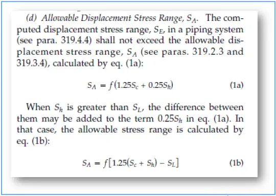
Allowable Displacement Stress Range (SA)
- SA is defined in equations (1a) & (1b) of ASME B 31.3 (Reproduced below)
- SA is a function of the cyclic factor f
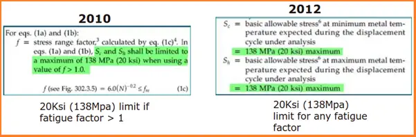
The definition of f has changed over the years.
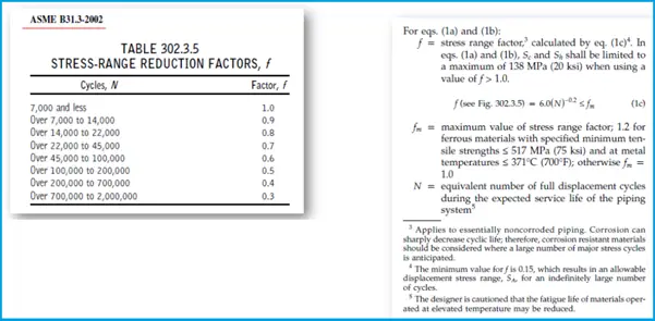
Sc and Sh are each limited to 20 ksi when calculating SA allowable displacement stress range.
Expansion Allowable Stress Change
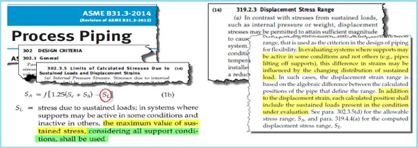
CAESAR II Has Always Determined & Used the “Maximum Value”.
But What Does “Considering All Support Conditions” Mean?
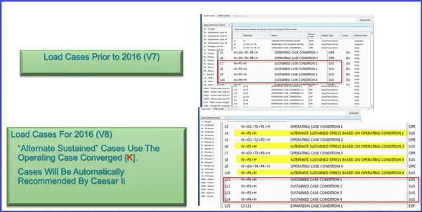
Alt Sustained (formerly Hot Sustained approach)
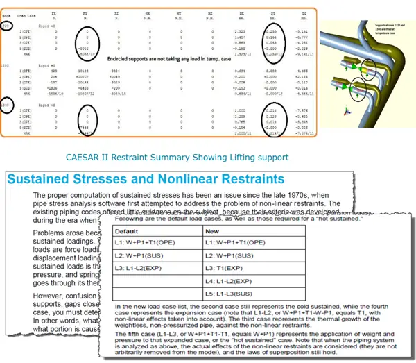
“… All Support Conditions (Positions) of The Pipe …”
- Each Operating Load Case (For a Particular Support Condition) Could Produce a Different Sustained Stress Distribution.
- The Expansion Allowable Must Be Based on The Maximum Sustained Stress, Considering All of These Operating Load Cases.
- Consider the following Example:
- Only 2 of The Branch Lines are Hot.
- One Branch Line is Cold.
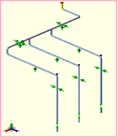
The system Has Three “Real” Operating Conditions, All Producing a Different Primary (Sustained) Stress State Due to Different Nonlinear Support Conditions.
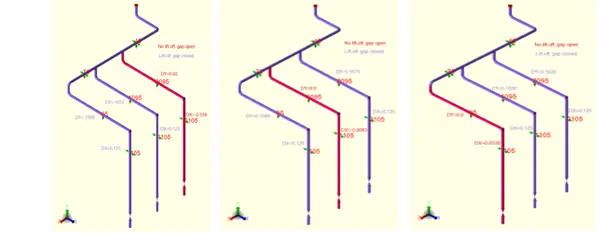
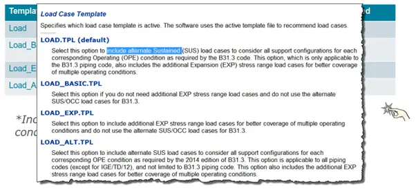
How Can This Be Achieved, Automatically In The Software?
New Load Case Template Recommendations
ASME B31J
- Standard Test Method for Determining Stress Intensification Factors (i & k Factors) for Metallic Piping Components
- The scope of this standard has recently been revised to add the ability to update new i & k Factor information as it becomes available
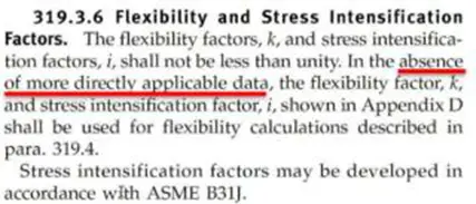
- B31J provides a set of calculations for revised SIFs and flexibility factors, as defined in the revision to ASME B31J. By using these revised SIFs and flexibilities, your stress analyses produce more accurate results. B31J provides the “more applicable data” referenced in recent editions of the piping codes.
What 319.3.6 is saying……
i-factor requirement as per the Latest Code
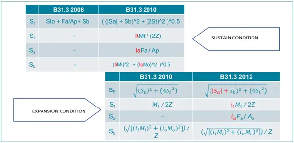
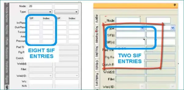
As shown in Figure the previous code (Appendix D) you had SIF(i) and SIF(o) which were valid for both Expansion Stress and Sustained Stress. Now you can find the following. Not only the SIF are different for the primary and secondary stress but in addition, you have to consider SIF for Tortion and axial effect!
- SIF is valid for Expansion Stress (SIF)and Index(SSI) is valid for Sustained Stress.
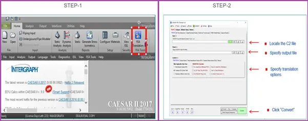
Do you know that the i & k factors from ASME B31.3/ASME B31.1 can be calculated according to B31J and it is freeware available with CAESAR-II software?
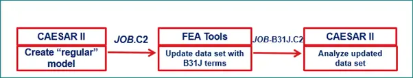
B 31J calculations in CAESAR II…..
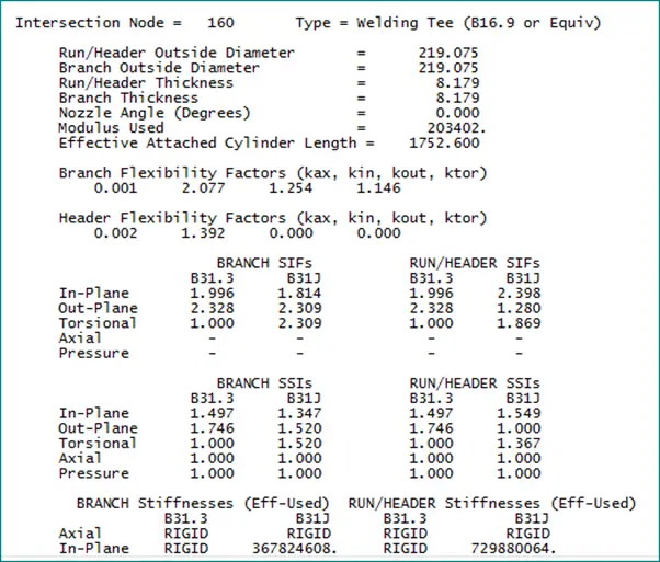
B 31J result for Flexibility (k) & SIF (i)…..
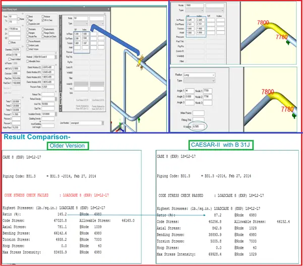
CAESAR-II model with “more applicable data”….
We open the translated model in CAESAR II using B31J option
Good morning,
Trust all are well.
I am a young but eager piping engineer using Caesar II on a daily basis.
I often end up on your platform learning something new.
Recently, I have been asked to do a CII analysis on a GRP system according to ISO 14692-2017.
After some iterations on the routing, I asked myself this question.:
1. – Do I model GRP Tee’s the same way as metallic piping?
2. – What is actually now the right way of modelling Tee’s in CII.
Since I end up modeling a few ways to see which one gives me the highest stress – And which is also very time-consuming with various models.
Thus the reason why i am messaging you. – Please help.
I do not know really where to find literature about how to model Tee’s in CII – And the forums have to many discussions. I would like to have someone just break it down for me.
I did go look at the illustration in ASME B31.J.
But this is usually how I would normally model it:
1. I’ll model in the run pipe. > Then the Tee section to the middle of the Tee > Then the other section of the Tee > Then continue with the run pipe.
2. Then model the the branch from middle of the Tee > To the outer dim of the tee-branch to the but weld location. > Then continue the branch.
3. Then add SIFs on the both the Tee elements at the node connecting the two Tee elements and tee-branch.
4. Then Adding the SIF to the same node on the tee-branch element.
This would be my first run.
Then I would break up my tee-branch element in two if the d/D<0.5.
Where the element from the middle of the Tee to the outer edge of the run pipe will be a rigid = 0Newton
The SIF will be removed from rigid element and the SIF will be added to the tee-branch element on the sharing node between the rigid and tee-branch.
I do not C-node anything.
Am I doing it right or should I be modelling it differently?
Kind Regards,
Sydney