Spring hangers are an integrated part of the Piping Industry. The use of spring hangers for supporting pipe weights is well-known to every piping engineer. Whenever some rigid supports are not taking load due to their thermal movement or rigid supports are creating bad effects on equipment connection Piping engineers suggest the use of a spring hanger to share some of the loads and to keep the piping system safe.
The selection of the appropriate type of hanger support for any given application is governed by the individual piping configuration and job requirements.
There are two types of Spring hangers.
- Variable Spring Hanger- Loads vary throughout its operating range and
- Constant Spring hanger- The load remains constant throughout its operating range.
The following write-up will provide a simple guideline for the selection of both Variable and constant Spring hangers while analyzing a piping system using Caesar II.
Selection Procedure of Variable Springs
1. Determine the hot load required and the pipe movement (up or down).
2. Estimate the travel range from the catalog.
3. Select the smallest spring size which has the hot load within the working travel (mid-range).
4. Ensure that the cold load lies within the working range of the spring i.e. between the two dark black lines shown in the selection chart. Calculate the cold load as follows:
- Cold Load = Operating Load + Movement x Spring Rate (For pipe movement up) or
- Cold Load = Operating Load – Movement x Spring Rate (For pipe movement down)
5. If the Cold load lies beyond the working range in the selection chart, then select a higher spring size or the next travel range.
6. Check the variability in selected spring
Generally, for non-critical systems, the variability is limited to 25% throughout the total travel. For critical systems such as steam connections terminating at turbines and pipes connected to rotating equipment Like compressors etc. variability is limited to 10%. If the variation exceeds the allowed value, choose a higher-size spring or smaller spring rate at the same load range.
7. Select the type and check the feasibility of the spring depending on the space available and the type of structure available.
Selection procedure of Constant spring hanger
Constant Effort spring shall be selected where the vertical movement exceeds 50 mm, where it is necessary to restrict the transfer of load to the adjacent terminal of equipment, or where the Spring variability exceeds 25%.
1. Determine the load and total movement.
Total movement = design movement + overtravel Overtravel = 20% of the design movement or 25 mm whichever is higher.
2. Select the spring from the load chart keeping in mind that the spring selected must lie within the working range (Between red and black lines)
3. Select the type and check the feasibility of the spring depending on the space available and the type of structure available.
4. The Spring box must be able to move freely without any restriction.
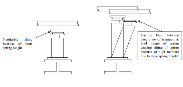
5. Stress Engineer must check the eccentricity (See Fig 1 below) of the spring load flange and the spring base plate while providing foundation information to the Civil team.
Spring Hanger Selection procedure in Caesar II
1. CAESAR-II Default Setting for Hanger Selection: Before making input for spring selection it is always better to make a default Caesar setting for the hanger design.
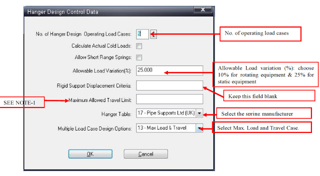
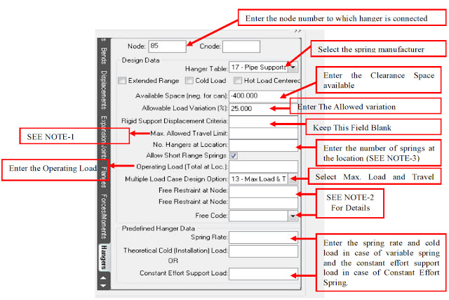
2. CAESAR-II Auxiliary Spreadsheet setting for Hanger Selection During spring selection at a particular node, the following auxiliary spreadsheet appears. The setting of this spreadsheet is to be done as illustrated in the below diagram.
NOTE-1: Maximum Allowed Travel Limit: This field is used to specify a limit on the amount of travel a variable support hanger may undergo. CAESAR will be forced to select a Constant Effort Spring if the movement exceeds the limit in this field, even though a variable effort spring would have fulfilled our purpose. Constant effort hangers can be designed forcefully by inputting a very small number i.e. 0.001 in this field.
NOTE-2: Free Code: Anchor or Restraints from equipment connections which are very near to the hangers are usually freed during the hanger design restrained weight run so that loads normally going to the equipment nozzle is carried by the hanger. The hanger can be designed to take almost the full weight of the pipe between the anchor and the hanger Using this field enter the node number & the direction in which free code is to be used.
Free Codes are:-
- Free the anchor or restraint in the Y direction only.
- Free the anchor or restraint in the Y and X directions only.
- Free the anchor or restraint in the Y and Z directions only.
- Free all translational degrees of freedom for the anchor or restraint. (X, Y, and Z)
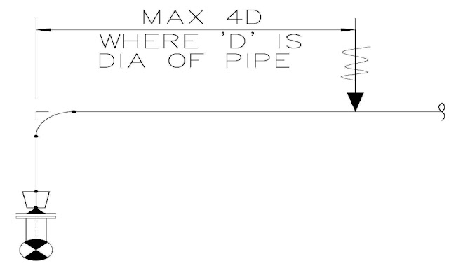
- Free all translational and rotational degrees of freedom for the anchor or restraint. (X, Y, Z, RX, RY, and RZ).Refer to the Figure below.
Option 5 above usually results in the highest adjacent hanger loads, but should only be used when the horizontal distance between the hanger and the anchor is within about 4 pipe diameters as shown in Fig 4.
NOTE-3: Number of hangers at location: For better stability, the base type spring support of 24″ and larger are used with 2 spring cans.
Few important points to keep in mind while Spring selection
- For the can type springs the spring height should be kept minimum from a stability point of view. If the spring height is less the moment of spring will reduce and the tilting of the spring (Fig. 5) can be avoided or significantly minimized.
- The spring which has a lower spring rate will have lower load variation.
- While designing the spring hanger the sustained sagging should be minimized within +/-1 mm so that the original piping system is not strained much.
Few more useful Resources for you…
Technical and General requirements for Spring Hangers while purchasing.
TBE of vendor Spring hangers: Main points to consider before placing an order
Spring hangers: Common Interview Questions with Answers
Spring hanger selection and design guidelines for a Piping engineer using Caesar II
Basics of Pipe Stress Analysis


Thanks for a marvelous posting! I quite enjoyed reading it, you may be a great author.I will ensure that I bookmark your blog and will eventually come back sometime soon. I want to encourage yourself to continue your great work, have a nice evening!
Greetings from Los angeles! I’m bored to death at work so I decided to check out your blog on my iphone during lunch break. I really like the information you provide here and can’t wait to take a look when I get home. I’m surprised at how fast your blog loaded on my phone .. I’m not even using WIFI, just 3G .. Anyhow, superb blog!
Wow, that’s what I was looking for, what a stuff! present here at this weblog, thanks admin of this web site.
hi ,This is a great website and I found a lot of useful information here. Thanks very much. But I have one problem: All the .bmp pictures in the article cannot be shown in my computer and only the .jpg pictures can be shown. Could you give me a solution? For example, I can see all the pictures in but not in …
please explain about hold-down hanger and about how to modeling it in caesar.
thanks
why I cant see the pictures ?
What does No. of hanger design operating load cases in hanger design control data window physically signify?and how does this value relate to static load cases?how to add hanger wt to each load case?wht hanger stiffness to be defined against each load case.