
Stub-in and Stub-on are methods for making a fabricated branch connection from the pipe. Both types are permitted by many international codes and standards, including ASME B31. However, both of these are weak connections on piping systems and are normally limited only to low-pressure and temperature applications. In this article, let’s explore the differences between Stub-in and Stub-on branch connections.
What is Stub-In?
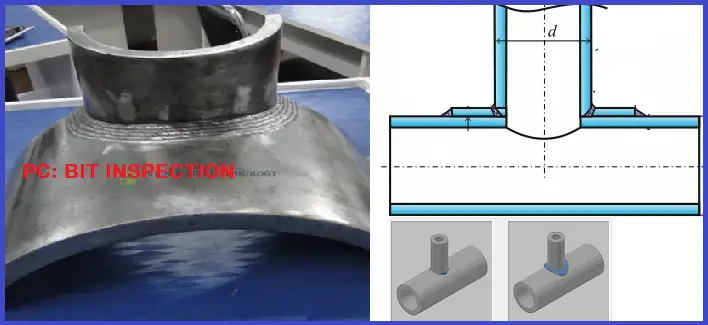
In the case of a stub-in, a larger hole is drilled in the header or run pipe, and a branch pipe whose end is contoured similar to the inside diameter (ID) of the header is fitted inside the hole. Then both the stub-in branch pipe and the run pipe are welded together to form a connection similar to reducing tee. Stub-in is normally used when the branch is more than one size smaller than the main pipe. For the “stub in” connection, the branch pipe extends to the inside of the main pipe. Stub-in connection is also known as the set-in connection.
What is Stub-On?
On the contrary, In the case of a Stub-On branch connection, the hole that is cut in the run pipe is the same as the inside diameter (ID) of the branch Pipe (Not the Header). The end of the branch pipe connection is contoured the same as the outside diameter (OD) of the header pipe and is then fitted outside the hole on the header pipe. It looks like the branch is seated “onto” the header pipe. Stub-on is generally used when the branch is equal to or one size smaller than the main pipe. For “stub on,” the stub extends only to the outside of the main pipe. A stub-on connection is also known as a set-on connection.
Additional Features for Stub-In and Stub-On
Both stub-in and stub-on branch connections can be made with or without a reinforcing pad as per requirement. This requirement is normally governed by pressure and stress criteria. The reinforcement pad is basically a ring that is cut from the run pipe or from a plate with the same material as the run pipe. At the center of the pad, a hole is made (the size the same as the branch pipe). When it is cut from a flat plate, it is contoured to fit around the run pipe. The width of the reinforcement pad is normally one-half the diameter of the branch pipe.
The aim of this reinforcement is to substitute the material that was removed for making the branch connection from the header. A small-diameter hole, known as a weep hole (1/4″ NPT) is normally drilled in the pad, which acts as a vent during the welding process for the weld-generated gases to escape. Using full penetration welds, The ring or pad is then welded to the branch and the run pipe. Once, the work is completed, the small hole is fitted using a plug.
Both the stub-in and Stub-on connections, in a sense, reduce the cost of pipe fittings. It saves installation time as well because only one weld is required around the stub hole instead of three welds that are needed for joining welding tee connections.
The welding strength of the Stub-in connection is as good as butt welding but welding steps are difficult in actual conditions. So Stub-in is comparatively stronger than stub-on connections.
Stress Considerations for Stub-in and Stub-on Connections
From the piping stress analysis considerations, the calculated SIF of stub-in and stub-on connections is much higher than weldolet fittings and ASME tees, which is significant when a detailed stress analysis is done on the system. While analyzing, extra caution needs to be considered as the stress generated will be higher. The use of this type of branch connection is not preferred for severe cyclic applications, high-pressure temperature applications, or category M fluid service applications.
Stub-in vs Stub-on Piping Connection | Differences between Stub-in and Stub-on
The main differences between a stub-in and stub-on branch piping connection are tabulated below:
| Stub-in pipe Connection | Stub-on branch connection |
| As explained above, Stub-in is used when the run pipe and branch pipe have a difference of more than one size. | On the contrary, a stub-on pipe branch connection is applicable when the branch pipe is equal to the run pipe or only one size lower than the header pipe. |
| In the case of the stub-in branch connection, the pipe welding between the branch and header is of butt-weld type. This welding is quite difficult. | Stub-on branch connections are made using fillet welds. Welding is easier as compared to the stub-in welding method. |
| A stub-in piping connection is able to withstand more pressure. | Stub-on branches are comparatively weaker than the stub-in branch connection and hence handle less pressure. |
| The branch edge of a stub-in connection matches the internal pipe diameter of the header. | For stub-on branch connection, the branch edge lies on the outside diameter of the header. |
| Stub-in pipe connections usually have more weld strength value than sub-on branch connections. | Stub-on pipe branches possess comparatively less weld strength value. |
Few more Resources for you..
Briefing about Reinforcement Pad
Piping Design and Layout
Piping Materials
Piping Stress Analysis
Piping Interface
Hellow Mr DEY I am regularly studying your post needless to say it’s very important for piping engineer. Thanks DIBYENDU CHATTERJEE mail chatterjeedibyendu50@gmail.com
In the video “stub-on” sketch the landing of 1.6±0.6 is wrongly marked, on the chamfer-side
Dear Anup Kumar Dey,
I am familiar with stub-in en stub-on connections. I can read and make isometrics. My question is how do you dimension on an isometric drawing the length of a stubpipe?
1) Do you dimension to the centre of the runpipe?
2) Do you dimension to the outside diameter of the runpipe?
3) or different?
Thanx in advance, from the Netherlands
Definitely piping dimensions usually takes it’s coordinate from the centre of pipe to the centre or end of the fitting at the other end of the stub. E.g. An Elbow, a Flange, Tee or Reducer, etc.
Therefore pipe stubs dimension is taken from CL of Header to the CL or the end of the opposite fitting.
Thanks. This is from a pipe fitter’s experience.
Always from center of the run pipe
Hello, I am Mahdi from Iran
Both methods can be used.
But two methods should not be used in a design project
I’m a young Structural & Mechanical Piping Engineer. Got a lot to learn. Wanted to thank you for sharing your knowledge and experiences.
Hi, thanks for the post, it’s clarifying! is there any general rules applied for when to use the reinforced pad or when it’s not needed? I mean, usually stub-in/on are used for non critical services already, but when to differentiate if the reinforcement is needed or not is 100% dependent from the stress calculations?
Dear Anup Kumar, I am a piping expert and I work in Iran, I would be happy to share our experiences.
If you are successful, send me your email address
Thankful
This article is incomplete and contains information that may not represent codes and typical design practices. These types of branches are allowed by many codes and are often limited to 25% of the nominal pipe size of the header or 4″ which ever is less. These branches may be used on high pressure piping within the allowable code requirements. The stub-on branch can be considered with an integrally reinforced branch fitting sometimes referred to as an o-let. These branches are not considered lessor by code, they are an option that needs to be designed within the code limits. They should not be used for large branches, over 25% of the header without specific engineering design and testing to ensure they are fit for purpose and meet code requirements. Code generally allows branches that are 2″ NPS or less and less than 25% of the NPS of the header without reinforcement. The welds for both stub-in and stub-on branches are designed to be full penetration welds and not fillet welds. API 1104 describes the branch weld as an open root groove weld with a fillet weld transition. External loading needs to be considered with branch design in addition to pressure containing capacity. ASME provides different stress intensity factors for each unique branch design, which needs to be considered. Stay safe out there.
Greetings
Good morning Mr. Patrick , May i request to you which particular reference code, that shows the 25% limitation of the branch pipe to be installed in the header. Thanks for your reply.
Good morning
Could you please advice me about the possibility of uning STUB IN method for air conditioning chilled & hot water pipe.
If it is possible, depending on which code?
If not, what are the reasons?