System Earthing or Grounding can be defined as a conducting connection whether intentional or accidental by which an electrical circuit or equipment is connected to the earth.
- Types of Grounding
- System Grounding
- Equipment Grounding
System Grounding
The System grounding is the intentional connection of neutral conductor to earth.
Purpose of System Grounding
- Controlling the voltage to earth within predictable limits
- Provides flow of current that will allow detection of an unwanted connection between system conductors and Ground and which may instigate operation of automatic devices to remove the source of voltage from conductors with such undesired connection to ground
Methods of Grounding
Ungrounded Systems (No intentional Grounding)
- Provides continuity of supply in case of 1-ph to ground faults
- No expenditure required for Grounding system
- Excessive overvoltages during arcing, resonance ground faults
Grounded Systems
- Greater Safety
- Freedom from excessive over-voltages
- Easier detection and location of ground faults
Resistance Grounded
- Limits earth fault current and subsequent effects on the connected equipment
- Reduces momentary line-voltage dip
- Control of transient overvoltage
Reactance Grounded
- Ground fault current should be preferably 60% of 3-ph fault current to prevent serious transient overvoltage. This is considerably higher fault current than resistance grounded system
Grounding Fault Neutralizer
- Reactance is tuned to System charging current so that the resulting ground-fault current is resistive and of low magnitude
- Current and voltage are in phase, So if a ground fault is in the air (insulator failure) it is self-extinguishing
- Solidly Grounded Systems: Direct connection for systems with Ro<=X1 and Xo<=3X1
Equipment Grounding
The Equipment grounding refers to interconnection and grounding of all non-electrical metallic elements of a system
Purpose of Equipment Grounding
- To reduce electric shock hazard to personnel
- To provide adequate current-carrying capability both in magnitude and duration to accept ground-fault current permitted by the overcurrent protection system
- To provide a low impedance return path for ground-fault current necessary for the timely operation of the overcurrent protection system
Safe Grounding Design
Objectives for safe grounding design
- To provide means to carry electric current into the earth under normal and fault conditions without exceeding any operating and equipment limits or adversely affecting continuity in service
- To assure that a person in the vicinity of grounded facilities is not exposed to the danger of critical electric shock
Safe grounding strives at controlling the interaction of the two grounding systems as follows:
- The intentional ground consisting of ground electrodes buried at some depth below the earth surface
- The accidental ground temporarily established by a person exposed to a potential gradient in the vicinity of the grounded facility
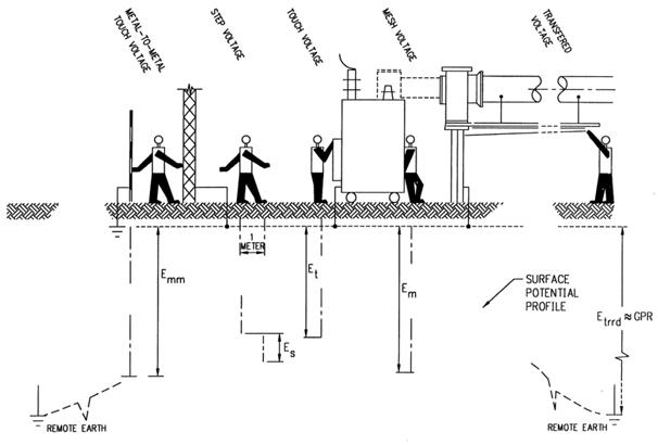
Basic shock situations (Fig. 1):

- Ground potential rise: The maximum electric potential that substation grounding grid may attain relative to a distant grounding point assumed to be at a potential of remote earth
- Mesh Voltage: The maximum touch voltage within the mesh of the ground grid
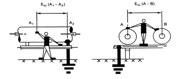
- Metal to metal touch voltage: The difference in potential between metallic objects within substation site that may be bridged by direct hand to hand or hand to feet contact
- Step Voltage: The difference in surface potential experienced by a person bridging a distance of 1m with the feet without contacting any other grounded object.
- Touch Voltage: The potential difference between ground potential rise (GPR) and the surface potential at the point where a person is standing while at the same time having a hand in contact with the grounded structure
- Transferred Voltage: A special case of touch voltage where a voltage is transferred into or out of substation from or to a remote point external to the substation site.
Metal to metal touch situation (Fig. 2):

Grounding Design
- Designed based on IEEE 80-2000
- Critical parameters for Design:
- Maximum grid current
- Fault Duration and Shock duration
- Soil resistivity
- The resistivity of the Surface layer
- Grid Geometry
General Concept of Grounding Design
- Combination of Vertical rods and horizontal conductors
- Horizontal conductors (grid) installed in a shallow depth (0.3 – 0.5m) are most effective in reducing the danger of high step and touch voltages on earth’s surface
- If the magnitude of current dissipated to earth is high it is seldom possible to install a grid with resistance so low so as to assure that rise of ground potential will not generate surface gradients unsafe for human contact. The hazard can be eliminated only by control of local potentials through the entire area by using ground rods.
Soil Treatment for Grounding
It is often impossible to achieve the desired reduction in ground resistance by adding more grid conductors or ground rods
An alternate solution is to increase the diameter of the electrode by modifying the soil surrounding the electrode by use of the following materials
- Use of Sodium chloride, magnesium and copper sulfate, etc.
- Use of Bentonite,
- Ground enhancement materials viz. Marconite, Terec+
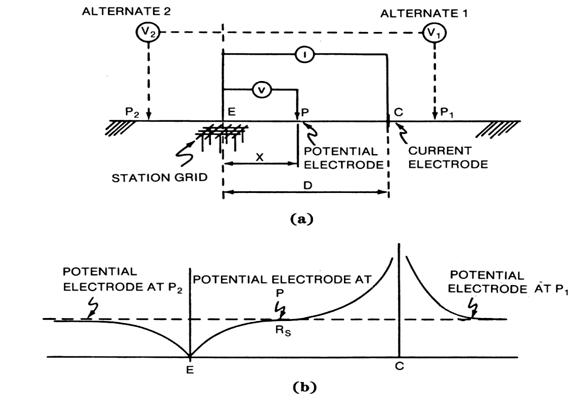
Field Measurements –Fall of the potential method (Fig. 3):
- Ground resistance measurement consists of measuring the resistance of the grounding system with respect to the remote ground electrode
- It has difficulties and errors when used for large grounding systems

Survey of Potential contours and Touch and Step voltages:
- Use the existing power lines and remote substation as current electrode
- Pass test current through substation ground grid via remote current electrode as in substation ground resistance measurements
- Measure Touch and Step voltages.
- The test values are multiplied with a ratio of actual fault current to test current to obtain potential under fault conditions.
- Disturbance due to noise and electrical interference influences the results.
A new approach of measurement: OMICRON CPC-100 can be used to generate current at a Lower and higher frequency than power frequency. Using digital filter algorithms the test set will measure only the signal with a frequency that is currently generated and filters out signals at other frequencies. Disturbance due to noise and electrical interference thus no longer influence the result.
