
Stress analysis of lines connected to API tanks is very critical. I am sure most of you have done stress analysis of lines connected to equipment nozzles. However, when it comes to tank nozzle, there are some differences, due to which the approach followed for equipment nozzle cannot be followed.
In the Stress analysis of lines connected to normal Equipment nozzle (Vessel, Column, Heat Exchanger, etc.), generally, there are only 2 things that we have to account for during Caesar modeling.
- Nozzle’s thermal movements, and
- Nozzle flexibility
But in addition to those two things, there are two additional points that we have to account for in the Caesar modeling during the analysis of tank connected piping system. These are,
- Nozzle rotations due to tank bulging, and
- Tank settlement
About the first two, i.e. Nozzle’s thermal movements and Nozzle flexibility, we all are well aware, therefore I will not be covering these in this article.
We will see other two effects, about which we may not be aware, or if aware, not very clear how to model these in Caesar and take care of these along with Nozzle’s thermal movements, and Nozzle flexibility.
So first in the current article, we will see Nozzle Rotation due to tank bulging.
What is this Tank Bulging?
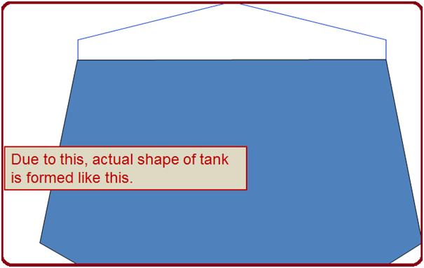
In the case of the tank, the tank is filled with liquid. This liquid has varying heights. Due to this, there is varying liquid pressure on the tank wall. It has more pressure at the bottom.
Due to this, the tank wall tries to expand more at the bottom (as seen in Fig. 1). But the bottom plate prevents this expansion and holds the bottom end of the shell in position. Due to this, the actual shape of the tank is formed similarly to as shown in Fig. 1.
This is called the bulging of the tank shell.
Due to the tank shell bulging, the nozzle on the shell moves radially outward, and rotates in the vertical plane, depending upon their position.
The nozzle on the lower portion of the tank rotates downwards whereas the nozzle on the upper portion rotates upwards.
This effect is not seen in other equipment, mainly because
- The equipment diameter is relatively much small (up to 3 m). Therefore the amount of radial growth is much less. Whereas tank diameters are generally large, of the order of 10 m to 60 m. Due to this the amount of radial growth is significant.
- Also, the equipment has internal pressure, not only pressure due to fluid weight. Thus pressure variation from top to bottom is not so much whereas, in the tank, pressure on top is zero.
- At the same time, the bottom of the equipment is not flat like a tank, which does not deflect but acts like a stiffener, to hold the shell ends.
However, the main difference is due to tank diameter only.
How Tank Bulging is calculated?
In the design code API 650, which governs the design of the tank, this bulging effect is covered in Appendix – P.
This Appendix – P is mandatory for tanks greater than 36 m in diameter and for tanks with a diameter of 36 m & below, it is optional or mandatory only if specified by the purchaser.
The intent of the 36 m diameter condition is to inform the user that the bulging effect is significant in large diameter tanks, which the code has considered as above 36 m diameter, hence put as mandatory.
For smaller diameters it is considered insignificant, hence kept as non-mandatory.
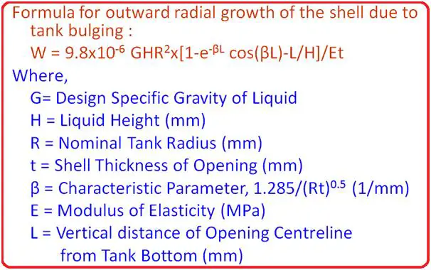
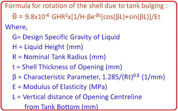
The formulas for the calculation of Radial movement and rotation due to tank bulging are provided in API 650 and produced in Fig 2 and Fig 3 for your reference.
If you calculate the outward radial movement and rotation using the above formulas it can be found that the effect of the tank bulging on the nozzle at a higher elevation is insignificant.
Pipe routing guidelines to minimize the effect of tank bulging:
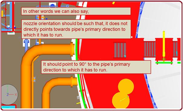
Due to bulging, the nozzle at lower levels rotates downward. This causes the pipe to move vertically downwards. To minimize the amount of this movement:
- Piping shall be rotated through 90° as close to the tank wall as practical. 2D (D=outer diameter of the pipe) spool may be provided to avoid elbow stiffening due to a flanged elbow. This is shown in Fig. 4
the software can calculate the radial and rotational. would u please explain how can i model the storage tank in the caser II or can model the tank as rigid and put displacement in the nozzle node (settlement or bulging).
Best regards
We faced failure of Water tank ( Colour coated tank made of sheets which are fixed by bolts and having liner inside. These tanks collapsed after shearing vertically. Can you throw some light on actual root cause.
do you have knowledge about the tolerance about bulge and depression? because as per API 650 B.3.3 stated that the maximum height of bulge or depth of local depression is measured by inches, I just want to know the acceptance criteria of it…
thanks..
“To minimize the amount of this movement:”
Can this movement during Tank loading and unloading be minimized by routing? I think you want to say the effect of this movement caused at the Shell and nozzle interface may be reduced. The 90-degree turn description with the snapshot is not clear. You may have to better explain this.