What is a Flanged Elbow?
Flanged pipe bends or flanged elbows are piping elbows connected with flange fitting to fitting. This means there is no spool or pipe piece in between the elbow endpoint( weld point) and flange. Flanged elbows are widely used for piping connections requiring compact pipe routing. Flanged elbows are purchased as a pipe fitting. On the other hand, flanged bends are prepared when a flange (weld neck or any other type) is directly welded to a piping elbow.
Types of Flanged Elbows
Based on the number of flanges connected to the pipe elbow fitting, flanged bends are of two types:
- Single Flanged Elbow and
- Double Flanged Elbow
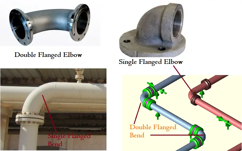
When one side of a pipe elbow is connected to a flange but the other side is connected to a pipe it is called a single-flanged elbow. Again when there are flanges on both sides of the elbows, it is called a double-flanged elbow. Refer to Fig. 1 for a typical example.
Effect of Flanged Elbow or Flanged Bend
When the flanges are attached near elbows or bends (Near Control Valve assembly and equipment nozzles); they exert a severe restraining force on the flexibility of the bend, thus reducing the flexibility of the bend and increasing the force and moment in the nearby support or nozzle. ASME B 31.3/ASME B31J Code provides two correction factors C1 and C2 to take care of the same effect. So basically the single-flange and double-flange options provide the following impacts in a piping system:
- Stress Intensification and Bend Flexibility changes
- Load values in the nearby support changes
- Calculated Force and Moment values at nearby nozzles increase
Flanged Bend Modeling in Caesar II
In Caesar II software the effect of the flanged bend can be easily taken care of by modeling flanged elbows as mentioned below.
Sometimes dummy/trunnion attachments at the elbow also provide a similar effect which is why a few organizations have the practice of using a flanged elbow while modeling the trunnions from the elbow.
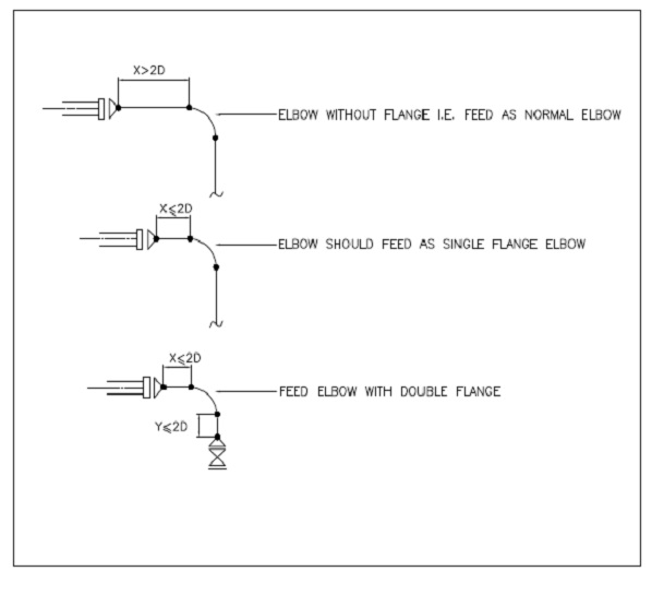
Single or Double Flange Option should be applied to Stress Analysis if there is any flanges or valves (heavy/rigid body) within two diameters (2D as per BS 806) of the ending weld point of the bend as shown in Fig. 2.
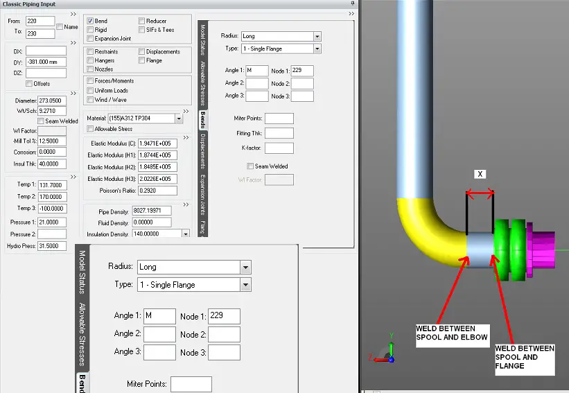
The modeling steps for the flanged bend are shown in Fig. 3. Single flanged bend is indicated by selecting 1-Single Flange as shown in Fig. 3. Similarly Double Flanged Bend can be indicated by selecting the 2-Double Flange option.