
Pressure Relieving Devices or PRDs are devices used in chemical, petrochemical, and power industries to prevent equipment from over-pressurization. As per the design requirements, these pressure-relieving devices function to relieve excess pressure generated in the system. PRDs are widely used for gas, steam, vapor, or liquid services. To protect operating personnel and equipment from unforeseen adverse impacts, pressure-relieving devices play an important role.
Pressure-relieving devices protect a vessel or item of equipment against overpressure and not against failure due to high temperature when exposed to fire, or failure due to corrosion. Safety in connection with such failures must be considered independently.
Types of Pressure-Relieving Devices
Various types of relieving devices used in process plants are as follows:
- Pressure Relief Valve or PRV
- Non-Reclosing Pressure Relief Device
- Pressure Safety Valve
- Relief Valve
- Safety Relief Valve
- Pilot Operated Pressure relief valve
- Pilot Assisted Pressure relief valve
- Rupture Disk
- Breaking Pin Devices
- Explosion hatch
- Liquid Seal
- Vacuum Relieving Devices
- Stellited Pressure Relief Valve
In the following paragraphs, we will learn about these pressure-relieving devices in brief
A. Pressure Relief Valve:
A pressure relief device actuated by inlet static pressure and designed to reclose and prevent the further flow of fluid after normal conditions have been restored.
The pressure relief valve is a generic term applied to relief valves, safety valves, safety relief valves, or pilot-operated pressure relief valves. A short Description of these valves is given at the end of this article.
B. Non-Reclosing Pressure Relief Device:
A pressure relief device designed to remain open after operation.
C. Safety Valve:
A safety valve is a pressure relief valve characterized by rapid opening or pop action. It is used for gas or vapor service.
D. Relief Valve:
A relief valve is a pressure relief valve, which opens in proportion to the increase in pressure over the opening pressure. Relief valves are generally used for liquids. In this type of valve, at the set pressure, the disk rises slightly from the seat without popping and permits a small amount of fluid to pass. As the pressure in the vessel increases, the disk is further raised; thus an additional area is available so as to allow an increased flow of fluid.
E. Safety Relief Valve:
A safety relief valve is a pressure relief valve that can be used in either vapor or liquid service. For vapor service, it is adjusted to give a “pop” action, for liquid service it is adjusted for gradual opening.
F. Pilot Operated Pressure Relief Valve:
This is a pressure relief valve in which the major relieving device is combined with and is controlled by a self-actuated auxiliary pressure relief valve (pilot). The use of pilot-operated pressure relief valves may be limited by the fluid characteristics (fouling, viscosity, presence of solids, corrosiveness) or by the operating temperature. The manufacturer should then be consulted.
G. Pilot-Assisted Pressure Relief Valve:
This pressure relief valve is a standard pressure relief valve (spring-loaded) fitted with an additional spring-diaphragm actuator to which a pneumatic signal is fed from a pressure-sensing pilot. The arrangement connecting the actuator to the spindle is such that the valve is still capable of operating as a standard safety valve in the event of pilot or actuator failure. The pressure relief valve will then open at 105 % of the set pressure as the valve spring set pressure is normally adjusted to 5 % higher than the pilot set pressure.
H. Power-Actuated Pressure Relieving Valve:
Movements to open or close are fully controlled by an external source of power (electricity, air, steam, or hydraulic). If the powder-actuated pressure-relieving valve is also positioned in response to other control signals, the control impulse to prevent over-pressure shall be responsive only to pressure and shall override any other control function.
It has to be noted that the power-actuated pressure relieving valve cannot be considered a safety device, since, unlike the others, it relies on an external source of power.
I. Rupture Disk Device:
A non-reclosing differential pressure relief device actuated by inlet static pressure and designed to function by the bursting of a pressure-containing disk. A rupture disk device includes the rupture disk or sensitive element and the rupture disk holder. Rupture disk devices are used either alone or in conjunction with a pressure relief valve. The application of rupture disks alone is limited by the fact that when the disk ruptures the entire contents of the system may be lost. They may, however, be installed in parallel with a pressure relief valve to provide the additional capacity; in this case, the relief valve is set at a lower pressure to limit rupture disk bursting to major disasters.
Rupture disks are pressure differential devices and the relieving capacity is therefore affected by the sizes and lengths of the inlet and outlet pipework.
J. Breaking Pin Devices and Spring-Loaded Non-Reclosing Pressure Relief Devices:
A breaking pin device is a non-reclosing pressure relief device actuated by inlet static pressure and designed to function by the breakage of a load-carrying section of a pin that supports a pressure-containing member. A breaking pin device includes the breaking pin or load-carrying element and the breaking pin housing. Breaking pin devices shall not be used as single devices but only in combination between the pressure relief valve and the vessel.
A spring-loaded non-reclosing pressure relief device is a pressure-actuated by means which permit the spring-loaded portion of the device to open at the specified set pressure and remain open until manually reset. It may be used provided the design of the spring-loaded non-reclosing device is such that if the actuating means fail, the device will achieve full opening at or below its set pressure. Such a device may not be used in combination with any other pressure relief device.
K. Explosion Hatch:
A hinged metal cover is placed over an opening in a vessel. The hatch consists of a hinged metal cover placed over an opening. It is used for vessels operating near atmospheric pressure and when the risk of explosion exists. Explosion hatches are not recommended for use at higher pressures, since the weight of the hatch will be excessive and this may prevent quick opening.
L. Liquid Seal:
Liquid seals can be used instead of pressure relief valves for set pressures below 10-15 psig, where relief valves are not considered reliable. Typical examples are the seal leg of a flare and liquid seals used in MEK units to protect the filters. The “U-tube” may be filled with water, mercury, or other liquid. Freezing of the sealing liquid shall be avoided by steam tracing or heating. Provisions for make-up and draining of the filling liquid should be made.
M. Vacuum Relieving Devices:
A vacuum can be the normal operating conditions of a vessel (e.g. Vacuum Towers) or an occasional event for vessels normally operating under pressure. This can happen due to internal vapor or steam condensation, pumping out, gravity transfer of liquids, loss of heating and temperature changes, etc.
In the first case, the vessel is designed to withstand a full vacuum. In the second case, the designer can choose between specifying the vessel for full vacuum or providing a vacuum relief device (valve or liquid seal) that permits the entrance of air, inert gas, or fuel gas, etc., to prevent vacuum conditions.
It is important to specify the actual temperature coincident with occasional vacuum conditions. This temperature may be appreciably lower than the normal operating temperature. Based on the pressure/temperature level when the occasional condition occurs, vessel specialists will check the wall thickness required, which may not have to be increased due to the lower temperature coincident with vacuum conditions.
N. “O Ring” Seat Seal or Stellited Pressure Relief Valve:
Pressure relief valves may leak when the operating pressure is above 90 % of the valve set pressure. It is possible to enhance the tightness of a spring-loaded pressure relief valve for max operating pressure up to 92 % of set pressure (above 92 % consider pilot-operated pressure relief valves), either with :
- an “O ring” seat seal; the compatibility of this seal with the product has to be carefully investigated,
- a stellited pressure relief valve.
Short descriptions of Safety valves and safety Relief Valves are given here.
Safety Valves and Safety-Relief Valves:
These are pressure-relieving devices for gases or vapors which have been specifically designed to give full opening with little over-pressure. The kinetic energy of relieving gas or vapor creates a pop action that opens the disk rapidly, reaching the full lift before maximum overpressure. There are two basic types of safety valves: conventional and balanced valves.
Conventional Type Relief Valve
Conventional relieving valves are shown schematically in Fig. 1. The following two situations are possible :
- If the bonnet is vented to the atmosphere, the backpressure acts with the vessel pressure against the spring force.
- If the spring bonnet is vented to the valve discharge rather than to the atmosphere, the backpressure acts with the spring force.
If the superimposed backpressure were constant, (no matter what its value), it could be taken into account in adjusting the spring loading so that the relief valve would open at the required set pressure. In practice, however, the superimposed back pressure is generally not constant and varies between a minimum, which corresponds to the flow of purge gas alone in the flare system (no valve discharging), and a maximum which corresponds to the design flow of the flare system.
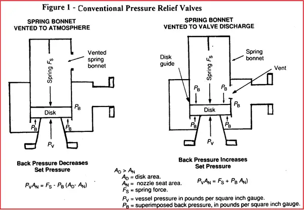
For a conventional valve of type B, the ‘spring’ set pressure is equal to the design pressure minus superimposed back pressure; therefore the valve will open above the vessel design pressure if the superimposed back pressure is higher than expected, and will open below design pressure if the superimposed back pressure is lower than expected.
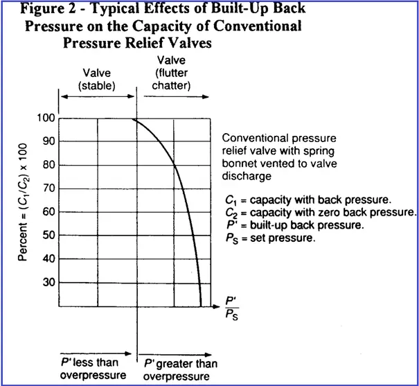
In order to avoid opening the valve at pressures too different from the required set value (as a result of variable superimposed back pressure), the first step is to only accept the use of conventional relieving valves when superimposed back pressure varies over a range not exceeding 10% of set pressure (gauge). However, this is not always sufficient because the flow performance after opening must also be examined. When the valve is open, the built-up backpressure tends to unbalance the equilibrium between spring force and vessel pressure. For a conventional valve of type B, this may result in a reduction of valve opening and a rapid fall of capacity (see Fig. 2). Therefore conventional valves, even when acceptable from the point of view of superimposed backpressure, must be checked with regard to built-up backpressure. The designer must check that the difference between the maximum value of backpressure and the minimum value of superimposed back pressure does not exceed 10% of the set pressure (gauge).
Balanced Type Pressure Relief Valve
Balanced safety relief valves are those in which the back pressure has little influence on the performance characteristics.
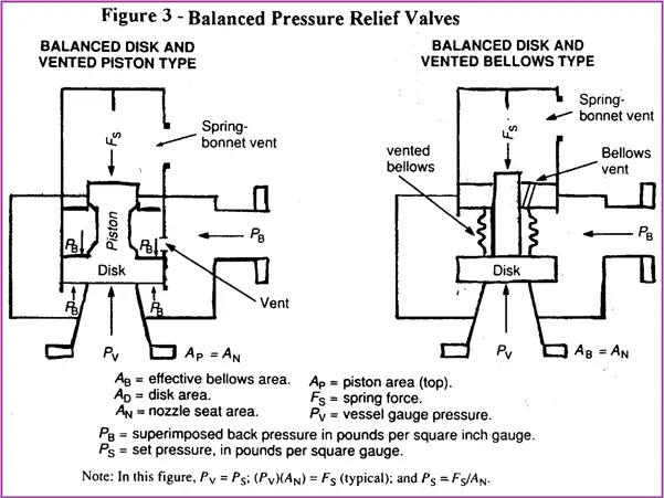
Piston type and Bellows type are available, the latter being more widely used (See Fig. 3).
Bellows Type Pressure Relief Valve-
The effective bellows cross-sectional area is equal to the nozzle seat area; disk areas extending beyond the bellows and beyond the seating area are equal and forces developed over those areas cancel each other.
The area under the bellows is kept under constant pressure by venting the bellows to a source of constant pressure, which is often the atmosphere unless the fluid that would be vented in case of bellows failure is dangerous; in that case, the vent should be discharged to a safe location, provided that its pressure is constant. Bellows valves have limited allowable set and outlet pressures.
If the maximum set or backpressure allowed for a single orifice appears too low, use a combination of smaller valves having an aggregate area equal to the valve in question. The use of smaller valves will permit higher set or back pressures.
Piston Type Pressure Relief valve-
In the piston type, of which several variations are manufactured, the piston guide is vented so that the back pressure on opposing faces of the valve disk cancels itself, and the top face of the piston, which has the same area as the nozzle seat area, is kept at atmospheric pressure by venting the bonnet.
Since gases may leak past the piston to the bonnet, the bonnet of piston-type valves must be vented in a safe manner.
Note that the vent on the valve bonnet should not be piped back into the flare header as its performance will then be the same as a conventional valve.
With balanced-type relieving devices, not subject to the limitations of back pressure set for conventional devices, the back pressure (superimposed and built-up) can be allowed to rise, permitting a reduction in size and cost of the relief header.
However, even when using balanced-type valves, when back pressure reaches 30% of the set pressure, the capacity of the valve for vapors and gases starts to fall below the theoretical capacity. With liquids, the capacity reduction starts at 15% of the set pressure. The fall-off in valve capacity depends also on overpressure, type, and make of valve used
For back pressures higher than this limit, valve size becomes progressively larger for the same flow, even if critical flow conditions are maintained. For back pressures higher than 50% of the set pressure, the valve manufacturer must always be consulted for valve sizing. In general, although there would be an incentive in increasing back pressure with balanced-type valves in order to reduce the size and cost of relief headers, values exceeding 30-35% of set pressure (gauge) should not be used without checking with an instrument specialist.
Good job! You thoroughly covered all important points with your post. I want to read more by you. Do you run any more blogs?
would like to know more about PRD.