
Meaning of Pump Alignment Checking
“Alignment Checking” this term is quite familiar to piping engineers and all construction engineers. During piping installation at the construction site, it is expected that the equipment flange should match perfectly (aligned) with the piping flange so that during bolting no problem occurs.
But achieving that perfect alignment is very difficult. If this alignment for rotary equipment is not proper then there may be several problems in the future during operation which may lead to vibration of equipment/piping system or in some situations equipment failure.
Code Guidelines Regarding Rotary Equipment Alignment
American Petroleum Institute code API RP 686 provides the data for acceptable deviation from the ideal perfect alignment. As per the code if the vertical and horizontal deviation of the piping flange and rotary equipment flange centerline is within 1.5 mm and parallelism (rotation) is within 0.0573 degrees then the alignment is accepted otherwise means to be devised to bring the deviation within those values.
While performing stress analysis of rotary equipment connected piping systems in Caesar II we can very easily ensure this limitation. The following write-up will describe the step-by-step method of doing the same.

Alignment check of nozzle flange shall be performed for all Rotating Equipment like Centrifugal Compressor, Steam Turbine, Centrifugal Pumps, Gear Pumps, etc as per the following procedure.
Alignment checking using Caesar II
Ensure the correct weight of the pipe (with proper thickness), Support weight (dummy pipe), Weight of valves, flanges, and any in-line items.
Consider Insulation density carefully (equivalent insulation density to be correctly fed with insulation & cladding weight, Check insulation on dummies for cold insulated lines).
Model all branch piping (like drip legs etc.) greater than 2 inches.
Discuss with a piping lead engineer the requirement of any maintenance flanges (Normally for steam turbine or centrifugal connected lines the maintenance flange is recommended) and include it if required.
Minimize the sustained load on the equipment nozzle as much as possible during the static analysis run of the Caesar model.
Normal industry practice is to analyze the Alignment checking in a separate file. So rename the static file as Filename_Alignment.C2
Make the equipment nozzle anchor flexible or remove the displacement if the anchor was not modeled. You can delete the equipment also if required.
Wherever spring support is used, define spring rate and cold load in case of variable effort spring & Constant effort support load in case of constant effort spring.
After performing the above create one additional load case in Caesar II as mentioned below:
WNC+H SUS System with spring hanger
WNC SUS System without spring hanger
Set the spring hanger as “As designed”.(Two load cases can be generated for spring As designed and rigid condition)
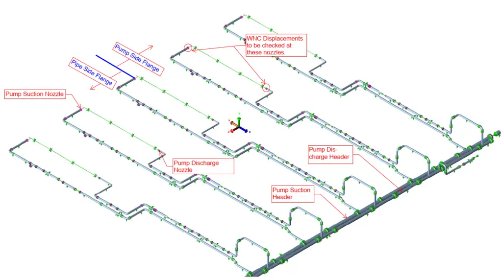
Now run the analysis and check the displacements of the nozzle at the above-mentioned load case (WNC or WNC+H, as applicable) and limit them within below mentioned values:
Vertical deflection (Normally DY): +/- 1.5 mm
Horizontal displacement (sqrt sum of DX and DZ): +/- 1.5 mm
Parallelism (sqrt sum of RX and RZ): 0.0573 degrees.
In case, the above limitations are not met then re-analyze by readjusting the spring and other supports and do the simulation.
Few Notes for Pump Alignment Checking
- An alignment check is to be performed for both inlet and outlet lines.
- An alignment check must be performed with the spring under both “As designed” and in “locked” condition.
- To avoid small misalignment in the vertical direction first support from the rotary equipment nozzle is used either spring support or adjustable type support.
- For top nozzles, the advantage of the equipment can be taken (with approval from the client) as the equipment flange will support the piping flange during alignment.
Few more Useful Resources for you..
Shaft Alignment Methodology for Compressor and Driver
Connection procedure (Alignment) of Process Piping with Rotating Equipments: An Article
Alignment Check Methodology in Piping Stress Analysis using Caesar II
Few articles related to Pumps
Piping Design and Layout Basics
Please clarify my following doubts
1)is anywhere mentioned the allowable displacement ?
2) please elaborate the below statement Set the spring hanger as “As designed”.(Two load cases can be generated for spring As designed and rigid condition) ?
1. allowable displacements are mentioned in API RP 686
2. As designed means spring should not be in locked condition.
Hii anup if I am providing operating load in spring hanger design, in alignment check can I remove the operating load and then I can check the alignment check kindly clarify.
Wrong
Api 686 specify to not use the spring unlock.
This modeling approach doesn’t seem correct.
The amount of misalignment is determined by field measurement, not analysis. If in fact, the connecting piping is offset from the equipment flange by the allowable 1.5mm in the Y or Z direction for example, then the correct way to analyze that would be to assign an internal strain equal to 1.5mm in that direction, exactly like a cold spring load but out-of-plane. The piping flange would need to be pulled in order to be aligned with equipment flange, and that pulling would create a strain load.
Not sure if Caesar can consider an out-of-plane strain. P-Delta would be needed in order to properly consider a strain load. Strain load would be added to other applied loads.
I have come across many installations. From manufacturers end they will requesting us to release spring during parallelity check. I never allowed that, I take guarantee and will show parallelity only with spring in locked condition. Parallelity is only for fabrication and erection check, not for design.
As per my understanding
We have to check only.
WNC + H (Spring Rigid)
Why we have to check WNC + H (Spring As designed).? For large bore piping how to align piping, if Cold Load is High? Spring will be Locked Right?
kindly Reply.
I have been present in several pump alignemt before commissiong and the check is done with spring locked.
So from the check WNC + H (Spring As Rigid) you can estimate if your deflections or rotations are within thea allowanble ones.
Instead you have to do check forces and moments on the nozzle by WNC + H (Spring As Design) load case because you will have a temporary condition between pre-commissioning and commissionig (spring unlocked) where there isn’t fluid inside the pipe so the spring (calculated considering fluid weight) can overload the nozzle.
This type of check can be really complicated, and frustrating if you skip a step. I appreciate your going over the different things that need to happen and the different things about your particular piping that you may need to consider. Many of these things I have been forgetting to consider. Thank you for such a helpful article and for the interesting information on this specific process.
the way to approach the real situation will be different considering your involment or point of view ,this simulation has been the eternal problem not only for this program for all designers ,but it is another way ,at the end of the day we must be sure in the field to have the proper values in order to install the gasket and monitor during torque how the machine react ,we call “Dial come back to zero”
“Wherever spring support is used, define spring rate and cold load in case of variable effort spring & Constant effort support load in case of constant effort spring.
After performing the above create one additional load case in Caesar II as mentioned below:
WNC+H SUS System with spring hanger
WNC SUS System without spring hanger
Set the spring hanger as “As designed”.(Two load cases can be generated for spring As designed and rigid condition)”
Sir,
This may be because, I am a novice in this field.
I am having problems in understanding, the above points.
Please elaborate.
I have check API 686 and could not find deviations as you mentioned above. Could you be more exact where you found those numbers?
It’s there i have read it
Dear All,
At the site, we are checking alignment but the values are about 6mm. The adjustable support is about 2.5m far from the nozzle which cannot be adjusted because the pump foundation everything completed.
Hence we are requesting to provide temporary support until final fixing. Please note that even we verify through stress analysis because of friction nozzle loads are exceeding and remaining supports are unbalanced. Kindly suggest
Anyone clarify my problem.One of the dehydration piping system inside valve crack developing,but not in piping,as i got from site photos and seen during valve uninstallation some misalignment in piping flange and valve its more than 30mm. This misalignment not in one axis almost 3axis .This problem how to analysis in Caesar software or any suggest from your point of view. Only
Thanks for your explain this knowledge.
I have a thought, like alignment check loads, we could revised like this:
1. WNC+H SUS(As-design) System with spring hanger
2. WNC+H SUS(Rigid) System with spring hanger
3. WNC SUS System without spring hanger
HI. MY NAME IS KAJA HUSSAIN, I AM A STRUCTURAL ENGINEER, NOW I AM WORKING WITH PIPING STRESS CALCULATION ALSO.
MY QUESTION IS, IF THERE IS TWO PUMPS CONNECTED TO A PIPING NETWORK, WHAT ALL CHECK NEED TO BE DONE?
It is clear in API 686, Chapter 6 Piping, 4.7.2, NOTE 2. It says spring hanger and spring support stops must be in place to ensure the piping system is rigid during the piping alignment check. No more argument is needed.