
ASME B31.3 is the bible of process piping engineering and every piping engineer should frequently use this code for his knowledge enhancement. But to study a code similar to B31.3 is time-consuming and also difficult because the contents are not at all interesting. Also every now and then it will say to refer to some other point of the code which will irritate you. But still, every piping engineer should learn a few basic points from it. The following literature will try to point out 11 basic and useful points from the code of which every piping engineer must be aware of.
1. What is the scope of ASME B31.3? What does it cover and what does not?
Ans: The Process Piping Code, ASME B31.3 is usually applicable for the piping systems in petroleum refineries; chemical, petrochemical, pharmaceutical, paper, textile, ore processing, onshore and offshore petroleum and natural gas production facilities; semiconductor, cryogenic plants; food and beverage processing facilities; and related processing plants and terminals. ASME B31.3 provides design, fabrication, erection, test, inspection, assembly, and material requirements for piping systems that carry the following fluids:
- Petroleum products
- Raw, intermediate, and finished chemicals.
- Refrigerants
- Gas, steam, air, water
- Fluidized solids
- Cryogenic fluids
Packaged equipment piping design is also covered by the B31.3 code.
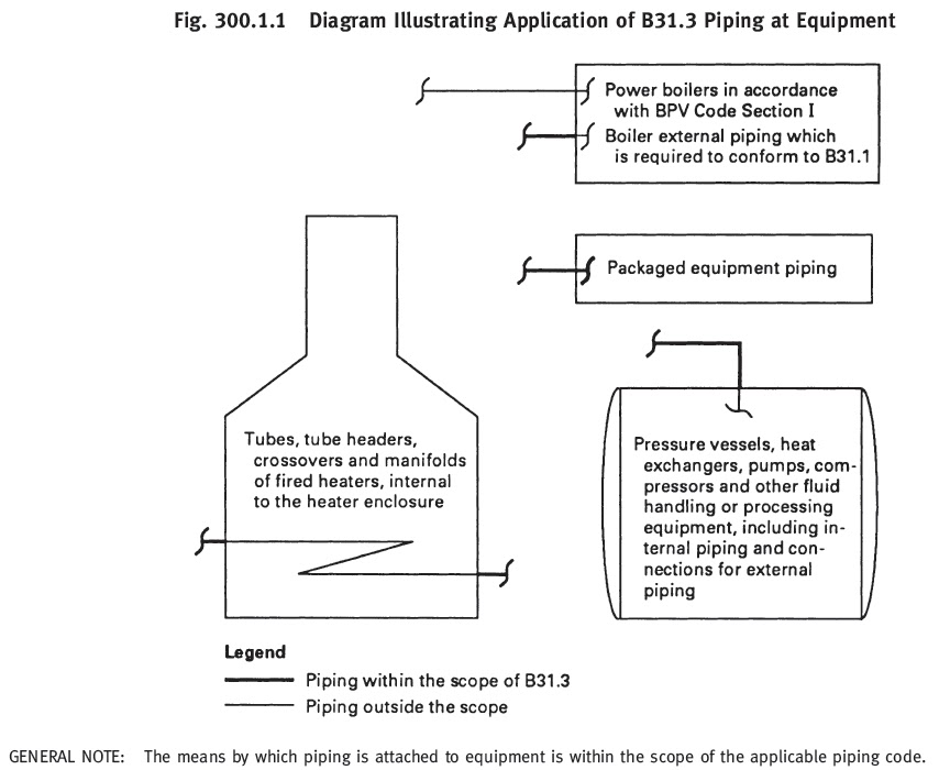
The process piping code ASME B31.3 typically does not cover the following:
- The piping systems designed for internal gage pressures at or above zero but less than 105 kPa (15 psi), provided the fluid handled is non-flammable, non-toxic, and not damaging to human tissues as defined in 300.2, and its design temperature is from −29°C (−20°F) through 186°C (366°F).
- Power boiler and power system piping following ASME B31.1
- Fired heater internal piping.
- Pressure vessels, heat exchangers, pumps, compressors, and other fluid handling or processing equipment, including internal piping and connections for external piping.
Alternatively, refer to the below-attached figure ( Figure 300.1.1 from code ASME B31.3)
2. What are the disturbing parameters against which the piping system must be designed?
Ans: The piping system must stand strong (should not fail) against the following major effects:
- Design Pressure and Temperature: Each component thickness must be sufficient to withstand the most severe combination of temperature and pressure.
- Ambient effects like pressure reduction due to cooling, fluid expansion effect, the possibility of moisture condensation, and build-up of ice due to atmospheric icing, low ambient temperature, etc.
- Dynamic effects like impact force due to external or internal unexpected conditions, Wind force, Earthquake force, Vibration, discharge (Relief valve) reaction forces, cyclic effects, etc.
- Component self-weight including insulation, rigid body weights along with the medium it transport.
- Thermal expansion and contraction effects due to resistance from free displacement or due to thermal gradients (thermal bowing effect) etc.
- Movement of pipe supports or connected equipments etc.
3. How to calculate the allowable stress for a carbon steel pipe?
Ans: The material allowable stress for any material other than bolting material, cast iron, and malleable iron is the minimum of the following:
- one-third of tensile strength at maximum temperature.
- two-thirds of yield strength at maximum temperature.
- for austenitic stainless steels and nickel alloys having similar stress-strain behavior, the lower of two-thirds of yield strength, and 90% of yield strength at temperature.
- 100% of the average stress for a creep rate of 0.01% per 1000 h
- 67% of the average stress for rupture at the end of 100000 h for temperatures up to and including 815°C.
- For temperatures higher than 815°C (1,500°F), (100 × Favg)% times the average stress for rupture at the end of 100000 h. Favg is determined from the slope, n, of the log time-to-rupture versus log stress plot at 100 000 h such that log Favg = 1/n. Favg shall not exceed 0.67.
- 80% of the minimum stress for rupture at the end of 100000 h
- for structural grade materials, the basic allowable stress shall be 0.92 times the lowest value determined (1) through (7) above.
4. What is allowable for Sustained, Occasional, and Expansion Stress as per ASME B 31.3?
Ans: Calculated sustained stress (SL)< Sh (Basic allowable stress at maximum temperature) Calculated occasional stress including sustained stress< 1.33 Sh Calculated expansion stress< SA = f [ 1.25( Sc + Sh) − SL] Here f =stress range factor, Sc =basic allowable stress at minimum metal temperature and SL=calculated sustained stress. The sustained stress (SL) is calculated using the following code formulas:
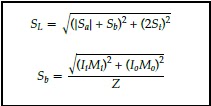
Here,
- Ii=sustained in-plane moment index. In the absence of more applicable data, Ii is taken as the greater of 0.75ii or 1.00.
- Io=sustained out-plane moment index. In the absence of more applicable data, Io is taken as the greater of 0.75io or 1.00.
- Mi=in-plane moment due to sustained loads, e.g., pressure and weight
- Mo=out-plane moment due to sustained loads, e.g., pressure and weight
- Z=sustained section modulus
- It=sustained torsional moment index. In the absence of more applicable data, It is taken as 1.00.
- Mt=torsional moment due to sustained loads, e.g., pressure and weight
- Ap=cross-sectional area of the pipe, considering nominal pipe dimensions less allowances;
- Fa=longitudinal force due to sustained loads, e.g., pressure and weight
- Ia=sustained longitudinal force index. In the absence of more applicable data, Ia is taken as 1.00.
5. What are the steps for calculating the pipe thickness for a 10-inch carbon steel (A 106-Grade B) pipe carrying a fluid with a design pressure of 15 bar and a design temperature of 250 degrees centigrade?
Ans: The pipe thickness (t) for internal design pressure (P) is calculated from the following equation.

Here,
- D=Outside diameter of the pipe, obtain the diameter from pipe manufacturer standard.
- S=stress value at design temperature from code Table A-1
- E=quality factor from code Table A-1A or A-1B
- W=weld joint strength reduction factor from code
- Y=coefficient from code Table 304.1.1 Using the above formula calculates the pressure design thickness, t.
Now add the sum of the mechanical allowances (thread or groove depth) plus corrosion and erosion allowances if any with t to get the minimum required thickness, tm.
Next, add the mill tolerance with this value to get the calculated pipe thickness. For seamless pipe, the mill tolerance is 12.5% under tolerance. So calculated pipe thickness will be tm/(1-0.125)=tm/0.875.
Now accept the available pipe thickness (based on the next nearest higher pipe schedule) just higher than the calculated value from manufacturer standard thickness tables.
6. How many types of fluid services are available for process piping?
Ans: In the process piping industry following fluid services are available..
- Category D Fluid Service: nonflammable, nontoxic, and not damaging to human tissues, the design pressure does not exceed 150 psig (1035kPa), the design temperature is from -20 degree F to 366 degrees F.
- Category M Fluid Service: a fluid service in which both of the following conditions apply:
- highly toxic fluid such that a single exposure to a very small quantity of the fluid, caused by leakage, can produce serious irreversible harm to persons on breathing or bodily contact, even when prompt restorative measures are taken.
- after consideration of piping design, experience, service conditions, and location, the owner determines that the requirements for Normal Fluid Service do not sufficiently provide the leak tightness required to protect personnel from exposure.
- Elevated Temperature Fluid service: a fluid service in which the piping metal temperature is sustained equally to or greater than Tcr (Tcr=temperature 25°C (50°F) below the temperature identifying the start of time-dependent properties).
- Normal Fluid Service: a fluid service pertaining to most piping covered by this Code, i.e., not subject to the rules for Category D, Category M, Elevated Temperature, High Pressure, or High Purity Fluid Service.
- High-Pressure Fluid Service: a fluid service for which the owner specifies the use of Chapter IX for piping design and construction.
- High Purity Fluid Service: a fluid service that requires alternative methods of fabrication, inspection, examination, and testing not covered elsewhere in the Code, with the intent to produce a controlled level of cleanness. The term thus applies to pipe systems defined for other purposes as high purity, ultra-high purity, hygienic, or aseptic.
7. What do you mean by the term SIF?
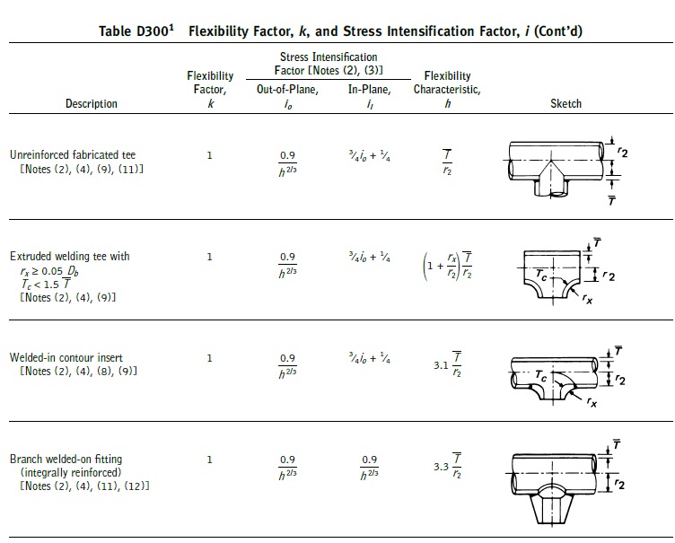
Ans: The stress intensification factor or SIF is an intensifier of bending or torsional stress local to a piping component such as tees, and elbows, and has a value great than or equal to 1.0. Its value depends on component geometry. ASME B31.3 Appendix D, up to edition 2018 used to provide provides formulas to calculate the SIF values which are reproduced in the following figure. However, From ASME B31.3 Edition 2020 onwards Appendix D is deleted from the code and the code now suggests using ASME B31J or FEA calculations to find the values of Stress intensification factors.
8. When do you feel that a piping system is not required formal stress analysis?
Ans: Formal pipe stress analysis will not be required if any of the following 3 mentioned criteria are satisfied:
- if the system duplicates or replaces without significant change, a system operating with a successful service record (operating successfully for more than 10 years without major failure).
- if the system can readily be judged adequate by comparison with previously analyzed systems.
- if the system is of uniform size, has no more than two points of fixation, no intermediate restraints, and falls within the limitations of the empirical equation mentioned below:
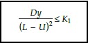
Here, D = outside diameter of the pipe, mm (in.) Ea = reference modulus of elasticity at 21°C (70°F), MPa (ksi) K1 = 208 000 SA/Ea, (mm/m)2 = 30 SA/Ea, (in./ft)2 L = developed length of piping between anchors,m (ft) SA = allowable displacement stress range U = anchor distance, straight line between anchors,m (ft) y = resultant of total displacement strains, mm (in.), to be absorbed by the piping system
9. How will you calculate the displacement (Expansion) stress range for a piping system?
Ans: Expansion stress range (SE) for a complex piping system is normally calculated using software like Caesar II, Start-Prof, Rohr-II, or AutoPIPE. However, the same can be calculated using the following code equations:
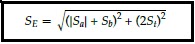
here
Ap = cross-sectional area of pipe
Fa = range of axial forces due to displacement strains between any two conditions being evaluated
ia = axial stress intensification factor. In the absence of more applicable data, ia=1.0 for elbows, pipe bends, and miter bends (single, closely spaced, and widely spaced), and ia =io
it = torsional stress intensification factor.
Mt = torsional moment range between any two conditions being evaluated.
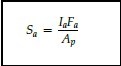
Sa = axial stress range due to displacement strains= (ia X Fa )/Ap
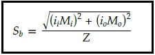
Sb = resultant bending stress range due to displacement strains.
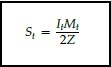
St = torsional stress range= (it X Mt )/2Z
Z = section modulus of pipe
ii = in-plane stress intensification factor
io = out-plane stress intensification factor
Mi = in-plane bending moment
Mo = out-plane bending moment
10. What do you mean by the term “Cold Spring”?
Ans: Cold spring is the intentional initial deformation applied to a piping system during assembly to produce the desired initial displacement and stress. Cold Spring is beneficial in that it serves to balance the magnitude of stress under initial and extreme displacement conditions.
When cold spring is properly applied there is less likelihood of overstraining during initial operation; hence, it is recommended especially for piping materials of limited ductility. There is also less deviation from as installed dimensions during initial operation so that hangers will not be displaced as far from their original settings.
However, nowadays most EPC organizations do not prefer the use of the Cold Spring while analyzing any system.
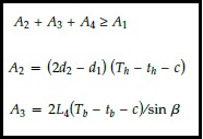
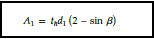
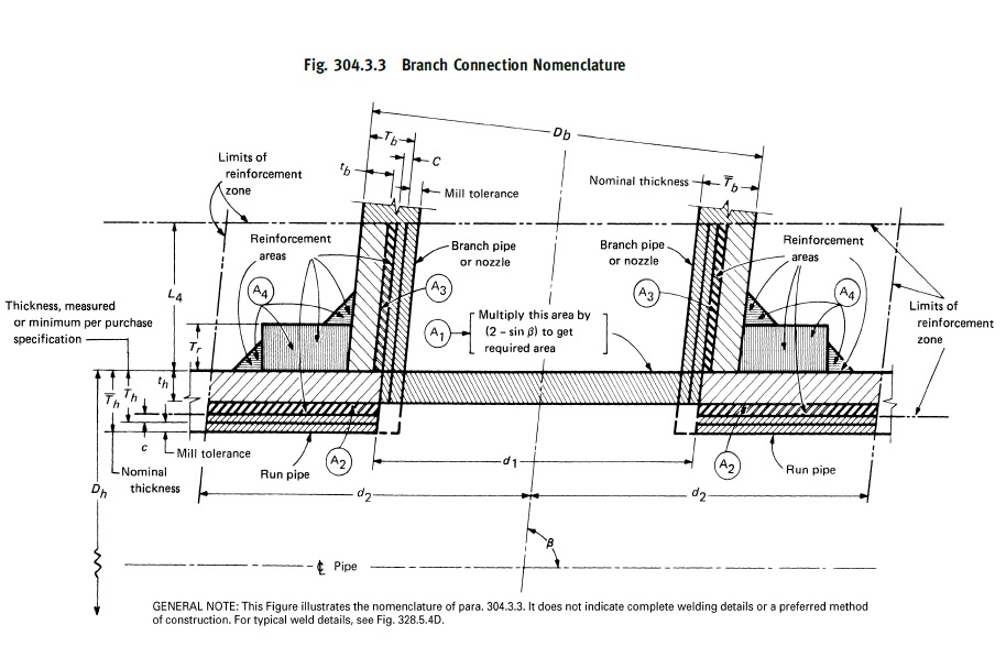
11. How to decide whether Reinforcement is required for a piping branch connection or not?
Ans: When a branch connection is made in any parent pipe the pipe connection is weakened by the opening that is made in it. So it is required that the wall thickness after the opening must be sufficiently in excess of the required thickness to sustain the pressure. This requirement is checked by calculating the required reinforcement area (A1) and available reinforcement area (A2+A3+A4) and if the available area is more than the required area then no reinforcement is required. Otherwise, additional reinforcement needs to be added. The equations for calculating the required and available areas are listed below for your information from the code. Please refer to the code for the notations used:
Few more piping stress interview questions with answers for you..
Spring hangers: Common Interview Questions with Answers
Interview questions with Answers for Jacketed Piping Stress Analysis
Piping Stress Job Interview questions and answers
Please clarify my following doubts
1) the equation provided for the sustain is bit different what i learned ( PD/4t+M/Z+F/A) ..but in your equation u havent consiederd longitunal stress but considered torsioanl stress.please clarify me?
2) in the equation for expansion stress tosional stress is to be corrected
please correct me if iam wrong
Regards
arun
Regarding your confusion:
I suggest you to read the latest version of the ASME B 31.3 code. Caesar used to calculate the stress following your equation as no code equation was available in earlier versions of the code. But now B 31.3 provides equations for calculating sustained stress.
The torsional term is also included in expansion stress calculation in latest version of the code.
Thanks for reading my blog. Request you to subscribe with your email to get instant updation about any of my posts.
Thanks for your quick reply ….and clarify my doubts
iam satisfied with your reply ..
1) still iam confused that why did they ddint use Longitudinal stress Pd/4t in new equation?
2) In previous version was also considered torsional stress in expansion stress as
Sqrt of Sb2 +4St2…………..in your equation 4st2 have changed to 2st2 .,..this also new changes in new version?
thankx in advance
arun
I find this site very informative. I have just attended an Intergraph C2 training for both statics and dynamic.
thank you for sharing
Dear Admin,
Please send basic material for learning CAESAR II software which you got during your training since i am new to this.
Hi there, I enjoy reading all of your article. I wanted to write a little comment to support you.
Good day! I simply want to give you a huge thumbs up for the excellent
information you have got here on this post.
I will be coming back to your site for more soon.
Heya i’m for the first time here. I found this board and I
find It really useful & it helped me out much.
I hope to give something back and help others like you aided me.
I like it when individuals come together and share thoughts.
Great website, stick with it!
Wow, this paragraph is nice, my younger sister is analyzing these things,
therefore I am going to let know her.
I couldn’t refrain from commenting. Very well
written!
Hi there! I could have sworn I’ve visited this web site before
but after looking at many of the posts I realized it’s new to me.
Regardless, I’m definitely delighted I came across it and I’ll be book-marking it
and checking back often!
Hi there, just wаnted to mention, I liked this blog post.
Keep on poѕting!
My Engineer advice me cut the dummy support 150mm which is suppose to be sit in the platform frame after cutting the grating as per design and welded in a pad for a fire water 250mm line .due to elevation difference of 25~ 40 mm they want don.t want to cut the grating rather than cut the horizontal dummy leg and weld it 25~40 mm below without shifting the pad or not weld addition pad. I can’t agree .Please suggest whether pad can be eccentric i.e on the top maximum 70 mm and on bottom 5mm from the OD of dummy leg.
Very nice..Keep it up..
Very informative web sits I like it
What is the maximum allowable deflection or permitted deflection for buried pipes?
Amazing! Its genuinely amazing article, I have got much clear idea
regarding from this article.
Good, This site has useful information. keep it up!
I have one question..
From where is the additional margin derived for higher allowable secondary stress limit compared to primary stress as per code ?
Of course, what a magnificent website and educative posts, I will bookmark your site. Have an awesome day!
By the way I have a query. How the insurance is effected in piping industry? Means if the process piping plants are covered under any sort of insurance. If it is so then how?
Where can I find info about installing relief valves? Got to prove a point, one must have at least same size relief outlet as inlet.
Hi,
first of all compliment for this really usefull & interesting internet site. I would like to ask you if the statement:
“Allowable stresses in shear shall be 0.8 times the basic allowables” par. 302.3.1 (b) is the unical limit to shear consideration in B31.3
The secondo thing I would like to ask you is if the meaning of the statement is that (having Fx and Fy shear component) Fx <= 0.8 Sh, Fy <= 0.8 Sh or if is the Resultant Shear force <= 0.8 Sh.
In the first case I will have single values of shear Fx and Fy to be used as allowable max forces applicable related to shear.
Is there any other limitation in Shear underlined by B31.3?
Regards
Lorenzo
pls tich me weidingtig wire ER308L calculat
Dears
I am designing one line blank (6″ 1500#) in a line with 2600 psi des. press and 260 F des.temp. and the selected material is A516 Gr.70. when i tried tocalculate the blank thickness using Para. 304.5.3 of ASME B31.3, i faced some issue. can anyone solve that. the issues are
1.E, quality factor is not available for A516 in table A-1A/B
2.S, stress value for A516 Gr.70 is available in 4 rows, so which one should select. if the temperature mentioned there (100,200 &300) is degree Celsius or Fahrenheit.
3.W, weld joint factor calls for 302.3.5(e), where note e. is not available so how to select that
please help me to sort out this.
How to calculate breadth and thickness of boiler using standards?
Can you please provide the same article on important points on B 31.1 for stress engineer?
Can AHMED B31.3 apply for GRP
Hi, design pressure is 330 bar and hence ASME Section VIII div 2 is applicable. However can we use ASME B31.3 instead of ASME Section VIII div 2? Pls suggest when to use which code depending upon design pressure? Thanks
Dear Anup, could you send me any example of the eq.16 for Formal Analysis Not Required? or where apply this case
Wonderful article and summarization of the key sections of ASME B 31.3