
What causes thermal expansion in piping?
All piping materials expand or contract when exposed to temperatures greater or lower than the installation temperature. As the temperature of the pipe material increases due to fluid temperature or sun/flare radiation, the pipe expands. Again, pipes contract as temperature decreases. Depending on the pipe materials, this pipe expansion or contraction varies. If this piping expansion or contraction is not addressed during the design of the piping system, it may lead to costly piping issues. In the world scenario, the piping system may fail and can be hazardous. Plant piping systems are usually exposed to very high temperatures and pressures. So, it is obvious that the length fluctuation from the maximum design temperature to the minimum design temperature must be taken care of during the piping system design for the safety and reliability of the system.
For example, if a pipe run is fixed at both ends and is heated, the liner pipe expansion due to temperature change will create compressive stresses on the pipe material. If the generated stress becomes so high that it exceeds the pipe material’s allowable stress, it may result in damage to the pipe, supports, or piping components. Depending on the severity of that damage, the plant may be required to go for a temporary shutdown to conduct repairs or replace the piping system prematurely.
As piping expansion and contraction due to temperature changes are unavoidable, the generated pipe thermal displacement must be absorbed in the piping system itself. There are methods by which piping expansion and contraction can easily be accounted for during the piping system design. In this article, we will learn the procedures to deal with pipe thermal expansion and contraction issues.
How do you calculate the Thermal Expansion or Contraction of a Pipe?
There are three parameters on which piping expansion or contraction depends:
Coefficient of thermal expansion (α): This parameter provides the amount of pipe linear expansion because of each unit change in temperature. The values of the thermal expansion coefficient are different for different materials. So, For the same length of pipe, the amount of expansion will be different for CS, SS, Aluminum, Copper, or Plastic pipes. So, indirectly piping thermal expansion depends on pipe material.
Length of Pipe/Pipeline Run (L): The more the length of the pipe, the more will be pipe expansion or contraction.
Temperature Change (∆T): Plant piping systems are designed from maximum design (hottest) temperature to minimum design (coldest) temperature throughout their service life.
The amount of thermal pipe expansion /contraction (∆L) can be calculated using the following equation:
∆L = L α ∆T (All values must be entered with the consistent unit)
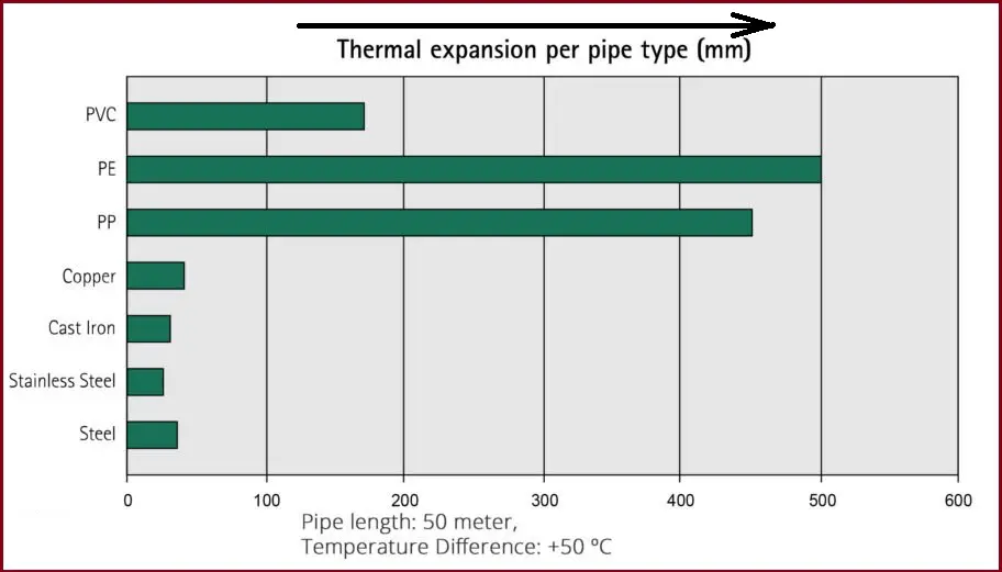
The following chart (Reference: walraven.com) gives an idea of how different pipe material expands with respect to temperature change. The chart is prepared considering a 50-meter pipe run with a +500C temperature differential.
Factors of the Material to Handle Generated Stress
To design for pipe expansion or contraction one needs to understand the following pipe material qualities:
Working Stress
Working stress is the maximum stress that the pipe material can handle during operation. All piping materials have the ability to withstand some degree of pipe expansion/contraction without sacrificing their structural integrity.
Modulus of Elasticity
The modulus of elasticity denotes the stiffness of the pipe material. It is an intrinsic property of the pipe material which provides the ability to elongate or compress upon the application of a force.
Pipe Outside Diameter
The pipe’s outside diameter affects the ability of the pipe to deflect stress. With an increase in pipe diameter, the rigidity increases and it is very difficult to deflect a rigid pipe.
How do you control pipe thermal expansion?
The best way to control the pipe thermal expansion or contraction is to design the piping system to account for it. The following paragraphs will explain the required steps.
Designing Pipe Systems for Thermal Expansion and Contraction
As mentioned earlier that the piping expansion and contraction issues need to be dealt with during the design phase to avoid significant problems at a later stage. There are four deflection mechanisms that can be employed to accommodate the pipe expansion inside the piping/pipeline system without losing integrity and reliability. These are:
- Changes of Direction
- Expansion Offsets
- Expansion Loops
- Expansion Joints
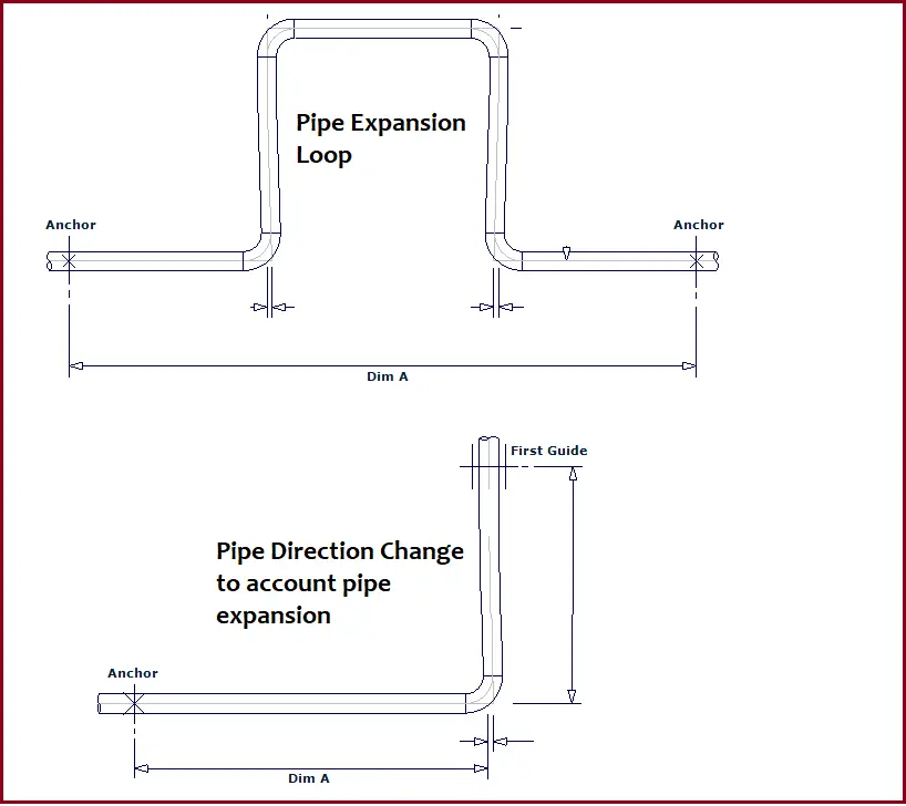
Pipe Direction changes to account Pipe Expansion:
The pipe route usually does not follow continuous straight lengths. Naturally, all piping and pipeline systems include changes in direction. These directional changes are a natural way of accommodating pipe thermal expansions within the piping system. If required, additional directional changes can be deliberately added by including pipe elbows and bends. The length of the pipe that runs perpendicular to a given pipe run is called the absorbing length. For example, if a pipe is running in the X direction; then adding pipe legs in the Y or Z direction is regarded as the absorbing length. The elbow along with the adjoining pipe allows some degree of thermal expansion. This required perpendicular leg length can easily be determined following the guided cantilever method.
Pipe Offsets to deal with Piping Expansion:
Expansion offsets are usually placed in the center of a pipe run. Each elbow accounts for some degree of pipe expansion. When it is required to absorb a small amount of thermal expansion or contraction pipe offsets work fine.
Pipe and Pipeline Expansion Loops:
Piping expansion loops are the widely used deliberate method to handle pipe expansion and contraction issues. Expansion loops can easily accommodate large pipe deflections. The required leg length is calculated using the guided cantilever method. anchors are provided on both sides of the expansion loop to direct the pipe expansion inside the expansion loop. There are various types of expansion loops that a piping or pipeline system can employ. More details about the pipe expansion loops are provided in the following article: Expansion Loops on the Piping or Pipeline Systems.
Expansion Joints to handle Pipe Thermal Expansion:
Expansion joints are mostly used in tight, enclosed areas when including expansion loops or offsets is not possible. Expansion joints are specialized assemblies that can absorb pipe thermal expansion or contraction. This is usually an expensive option and is used as a last resort. Most project specifications and codes instruct to avoid the use of expansion joints as much as possible. Click here to learn more details about pipe expansion joints.
Tutorial Video on Pipe Expansion Loop
Refer to the following video tutorial to learn more about pipe and pipeline expansion loops.
Is figure 1, which shows the difference in the coefficients of thermal expansion of various common materials, correct?
For your information:
Carbon Steel = 12.2 x 10⁻⁶
Copper = 16.4 x 10⁻⁶
Stainless Steel (Ferrictic) = 10.9 x 10⁻⁶
Stainless Steel (Austenitic) = 16.3 x 10⁻⁶
Hello Mr Anup Kumar Dey,
This is Nirav Bhow from Ahmedabad, India.
I am into the business of Design, Manufacturing and supply of Metallic Expansion Bellows since last more than thirty years.
Would like to be in touch with you for sharing experience and knowledge.
Thanks
Hi Mr Anoop Kumar
I was facing a problem for inserting the values expansion coefficient for new material in CAESAR II.
I have values for for HDPE pipe, 8 in/100ft for 100 deg F temperature difference. How can we put this values in CAESAR II material data base. In material data base they are asking to insert exp coef with respect to temperature. but we get the value for temperature difference. Also they are asking to put the value in 10 E 6 in/in but the actual value will be 10 E-6. can you please clarify.
your response in highly appreciated