
Expansion loops are fundamental in various piping industries involving higher temperatures including oil and gas, chemical processing, power generation, and HVAC systems, where temperature fluctuations can cause significant stress on piping networks. Even in pipeline systems where the length of the pipe is greater, expansion loops play a significant role in proper design even though the temperature is not higher. One of the most common methods used to manage thermal expansion in piping and pipeline systems is the expansion loop.
Why do we need Piping Expansion Loops?
Piping systems are often subjected to varying temperatures, either due to the fluid being transported or environmental conditions. As the temperature of a material increases, it expands, and when the temperature decreases, it contracts. This expansion and contraction can result in significant stress on the piping material.
All piping engineers are well acquainted with expansion loops in the piping systems. Whenever thermal displacements are more than a certain value these expansion loops are added to absorb the displacement inside the expansion loop. These are mainly required in any piping system design to
- Reduce system stress,
- Limit thermal displacements, or
- Limit Support Loads.
How Piping Expansion Loops Work
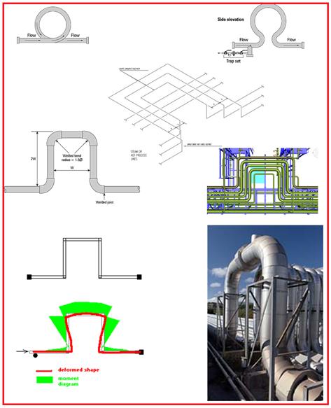
An expansion loop is a section of pipe that is intentionally bent into a U-shape, Z-shape, or similar configuration (Refer to Fig. 1) to absorb the thermal expansion and contraction of the pipeline. By introducing flexibility into the system, expansion loops allow the pipe to expand or contract without causing undue stress on the pipe or surrounding supports and structures.
Piping expansion loops are used to increase the flexibility of the piping system. To reduce the generated expansion stress and displacement caused by thermal expansion or contraction, legs perpendicular to the main piping system are provided. This perpendicular length is known as the length of the expansion loop. The more this expansion loop leg length, the better for the piping system. However, this leg length is limited by support feasibility, vibration tendency, and cost. That is the reason the length of the absorbing leg in an expansion loop is decided only to meet the requirement of stress qualification.
Piping expansion loops are widely used in long runs of pipes running over the pipe racks or sleepers. Pipeline expansion loops are usually provided at every 500 m length as the design temperature of pipelines is normally less as compared to piping systems.
Fig 1 shows typical loops used in the piping system.
Functions of Piping Expansion Loops
Expansion loops serve various purposes as listed below:
- Piping Expansion Loops provide the necessary leg of piping in a perpendicular direction to absorb the thermal expansion. They are safe when compared with expansion joints but take up more space.
- Load due to axial expansion causes bending stresses to be developed, increasing upwards in the vertical pipes and becoming a maximum at the loop elbows.
- That bending moment stays at that maximum bending moment level for the entire length of the top horizontal pipe until it gets to the next elbow and starts’ reducing until it reaches the bottom pipe on the other side of the loop.
- As the loop gets higher, both axial resultant stress in the horizontal pipes and the bending moments in the loop are reduced.
Types of Piping Expansion Loops
Piping Expansion loops are categorized into different styles:
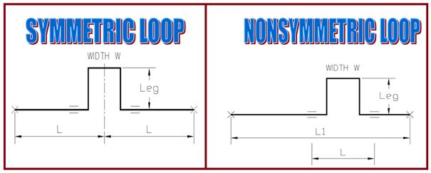
1. Symmetric loop vs Nonsymmetric loop (Fig. 2):
Ideally, loops shall be located centered between pipe anchors with equal legs on either side of the anchor. Symmetrical loops are advantageous in absorbing an equal amount of expansion from both directions.
When this isn’t practical make legs on either side of the anchor as equal as possible.
Friction Forces are determined by the number of pipes supporting a line crosser. By making these legs equal, the forces at the anchor should remain nearly balanced.
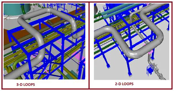
2. 2-D vs 3-D Expansion Loops (Fig. 3)
Expansion Loops may be 2-D (Two-dimensional loop) or 3-D (three-dimensional loop) types. Normally for steam lines, flare lines, condensate lines, and sloped lines, where there is the possibility of two-phase flow, 2-D expansion loops are preferred. Otherwise, the 3-D loop can be provided.
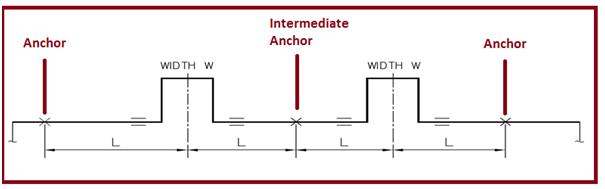
Requirements of Multiple Expansion Loops
More than one expansion loop may be required when:
- It is impossible to make branch connections flexible enough.
- Spacing between branches and neighboring lines or steel is limited.
- When the loop becomes too large to support or fit into the space available.
- Anchor forces become too unbalanced and steel cannot be economically braced.
- More than one expansion loop may be required when the forces required to bend the loop are too great, and the anchors cannot be economically reinforced.
- When the thermal displacements exceed the project’s specifically allowed displacements.
- When the length of shoe supports due to high thermal displacement is becoming too high it looks odd.
Placing Expansion Loops/ Expansion Loop Placements
- Loop width should always be based on utilizing existing supports.
- Thermal expansion must be allowed when spacing adjacent loops.
- Loop width does not have to be near 20 feet just because the loop nomographs happen to use that number. Loop width has only a secondary effect on results.
- Minimum loop height depends on the berthing of the line with respect to the location of the loop support.
- Piping Expansion Loops cannot extend too far beyond existing support or the overhang will cause the loop to “lose its balance.” This sets the maximum allowable loop height.
- The first two points have more influence on loop design than stress formulas, from the piping point of view.
- Three-dimensional expansion loops are widely used because this arrangement does not block the routing of low-temperature lines under the loop.
- Vertical loops are placed at road crossings and sometimes are nonsymmetrically located due to the location of the road.
Method for Sizing Pipeway Expansion Loops
Anchor lines near their center to determine which lines require loops by checking the allowable expansion at each end of the run. If the thermal displacement at each end is within the project-specific limit and will not clash with other lines, no expansion loop will be required. However, if the line spacing cannot be adjusted to take the movement, expansion loops need to be added.
Determine which of the lines requiring loops need the largest loop, second largest, etc., by the following:
- Multiply the total expansion of each line between its proposed anchors by the pipe’s moment of inertia (E). (The stiffness of a line is measured by its “Moment of inertia.”).
- The line with the largest of these calculated numbers will require the largest loop, the next smaller number, the next smaller loop, etc.
- The above rule does not check stress. This is checked after the loops are roughly dimensioned.
Fit the expansion loops between two pipe supports using the minimum spacing plus allowance for line expansion and bowing. Make the loops as wide as possible, but keep the height to a minimum. If stress or force is extremely high, check with the stress engineer for the height of the loop.
Send finished pipe way to stress for accurate calculation of anchor forces for transferring to Structural and accurate evaluation of stresses in the piping.
Estimating Expansion Loop Leg Requirement / Expansion Loop Calculator
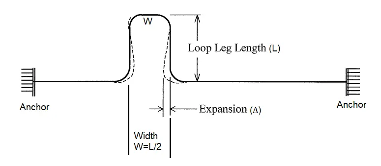
A preliminary estimate of the expansion loop absorbing leg requirement can be made from the equations derived from the guided cantilever method. As per that formula, the required absorbing leg, L (Refer to Fig. 5) for the piping expansion loop is given by
L=√(3ED∆/S)
where E=Elasticity modulus, D=Pipe OD, S=Allowable Stress at the maximum temperature, and ∆=thermal expansion.
Providing an expansion loop in a piping system needs additional space and additional elbows (additional cost) which may not be possible in some instances. In such a scenario piping expansion joints are used to absorb the thermal growth.
I have created an expansion loop calculator for preliminary loop sizing using the above-mentioned formula which can be downloaded by clicking here.
Frequently Asked Questions
Now that you have studied all the relevant sections regarding piping and pipeline expansion loops above, it is time to learn the following frequently asked questions:
What is a piping or pipeline expansion loop?
A piping or pipeline expansion loop is used in the systems to control the thermal expansion and contraction of pipes due to temperature variations. An expansion loop consists of bends/elbows and pipe sections designed in a specific way to absorb the movement and prevent stress on the piping system. They are usually located between two pipe anchors or buried parts in the aboveground piping/pipeline system.

What factors should be considered when designing an expansion loop?
When designing a thermal expansion loop, the factors that must be taken into consideration are:
- Pipe Material
- Temperature Differential (Install temperature to maximum and minimum design temperature)
- Pipe Diameter: With an increase in pipe diameter, it becomes more rigid which may call for more flexibility and thus increase in expansion leg length.
- Piping Layout: The layout of the piping system, including the placement of bends, elbows, and supports, affects how the thermal expansion is distributed. In a straight pipe run, thermal expansion will cause the pipe to elongate in the direction of the run. However, introducing bends and loops into the layout provides flexibility, allowing the pipe to expand and contract without imposing excessive stress.
- Loop Dimensions: The size of the expansion loop is determined based on the amount of thermal expansion expected and the allowable stress on the pipe.
- The required range of movement shall be considered.
What are the alternatives to expansion loops in piping and pipeline systems?
In a piping system, expansion loops can be avoided by providing suitable offsets. In critical systems where space is limited and offsets are not sufficient, expansion joints, bellows, or compensators are used as alternatives to piping expansion loops.
In large-size pipeline systems, the zig-zag pipeline route is followed to avoid pipeline expansion loops to optimize space requirements by pipeline loops.
What are the Advantages of Piping Expansion Loops?
The main advantages of expansion loops are that they are:
- Cost-effective
- Simple in design
- Can be easily installed
- Low Maintenance.
What are the Disadvantages of Expansion Loops in a Piping System?
Expansion loops need more space requirements for their installation and to work properly. So, sometimes where there is a space constraint, expansion loops may not be feasible.
Video Tutorial on Piping Expansion Loop
For further doubts kindly refer to the following video tutorial
Few more resources for you…
Expansion Loop and Rack Piping for a Piping Stress Engineer
Basics of Pipe Stress Analysis
Piping Design and Layout
Piping Materials
Piping Stress Analysis
Nice article on Expansion Loop.
However please make a note on 2D loop applicability:
– 2D loops can be provided for any services except for those required to maintain slope like flare headers which should be sloped towards KO drum. Hence Flare headers always will 2D loops (3D not allowed)
Good Article !! 3D loops may require drains which can be source weakness so minimize 3 D loops.
good article but loop calculation is missing which is more need .
Pls add the loop calculation in the comment section to help other readers. Later I will transfer it inti the main article.
I want to know that if there are some branches on the main pipe, then the angle of the branch would consider as a change of direction and there would be no need for expansion loop or offset. Or the length of the main pipeline is considered and the expansion loop is needed in between the branches?
Hi,
Could you guide how can we support for a vertical riser of DN600? The vertical length is around 12 to 13 meters.
Pipe material ASTM A 106 GR B. SCH 20.
Fluid Water
Max.temp. 40 deg.
Max operating pressure 15 bar.
Pipe is crossing almost 3 concrete floors and it is routed near by the RCC wall.
What is the best distance between the first guides and the expansion loop?
Very nice article dada…
Regards
Partha🙏
hi
dear Anup
does 60 mm expansion for a 92 m pipe need loop?
Hi sir;
i want to now how calculate the distance between two expansion loop
Thanks
Any suggestions on calculating anchor point loading?
Thanks
Hi sir, May i know the reason for the increase in pipe shoes length due to thermal expansion for expansion loop? where does this pipe shoe located? is it adjacent of the expansion loop or inside the expansion loop?
Don’t forget about pre-engineered flexible pipe loops. These function similarly, but are much more compact. See for “Flexible Piping Solutions”.
Hi friends,
I have a case here, where our pipeline in the vertical expansion loop is in the close proximity (apx 200mm) with other’s users’ line at both side of the loop in the same Piperack. Stress Analysis of our pipeline does not cover the expansion of other users line. How can I prevent my line hitting other users line in the extreme case ? Is it ok to put a limit support to my pipeline at the mid point of the vertical loop to prevent my moving beyond the calculated displacement of 80 mm ? Pls advice if there is any other alternative.
Enter the amount of thermal expansion, ∆ (Table C1/C1M from B31.3) = 90
Are u consider.
Kindly mark & share Screenshot of the Value in that Table C1/C1M from B31.3.