Requirement of Flexibility
Providing the required flexibility for absorbing the thermal movements of the piping system is one of the important activities in piping design. A rigid piping system experiences stress during operation at high temperatures. Providing sufficient flexibility in routing will ensure stresses in the piping system is within acceptable limits. So it is always suggested to be focused on providing flexible routing for large bore and temperature-critical piping. Flexibility in piping connected to strain-sensitive equipment like pumps, compressors, columns, turbines, plate heat exchangers, etc. is a must.
What it means!!!
- The piping designer should be aware of the stress and support concepts in piping layout which are the guiding principles behind flexible pipe routing.
- The piping designer should be aware of what pipe expansion means, how rigid piping induces stress and how to provide minimum expansion length using guided cantilever tables.
- The stress engineer is always there to review flexibility but the piping designer uses his best judgment and coordinates with the stress engineer as needed to design a flexible and stable pipe route upfront.
How does it help?
A basic stress concept will help the piping designer in many ways, like
- Understanding stress and flexibility concepts will help designers in reducing cycle time for the preparation of an effective layout that is acceptable to the stress engineer.
- Increases the technical expertise of the designer in piping layout and design and also gives a good understanding of pipe supporting norms.
- This will lead to better design, more effective and accurate material take-off & shorter schedule.
Some Critical Equipment & Systems:
- Pump suction and discharge piping (High temperature and sizes ≥ 12” more critical)
- Furnace and Reactor piping
- Column and Air Cooler piping
- Column and Reboiler piping – Two-phase flow
- Compressor piping
- Turbine piping
Examples of Flexible Piping:
Pump Piping (Column/Vessel to Pump)
- Provide sufficient pipe leg perpendicular to the pump suction axis so as to absorb suction line growth. Refer to Figure 1.
- Case 1 piping is more flexible as the column nozzle is perpendicular to the pump axis and pumps set equidistant from the column centerline help minimize differential thermal growth across the pump axis.
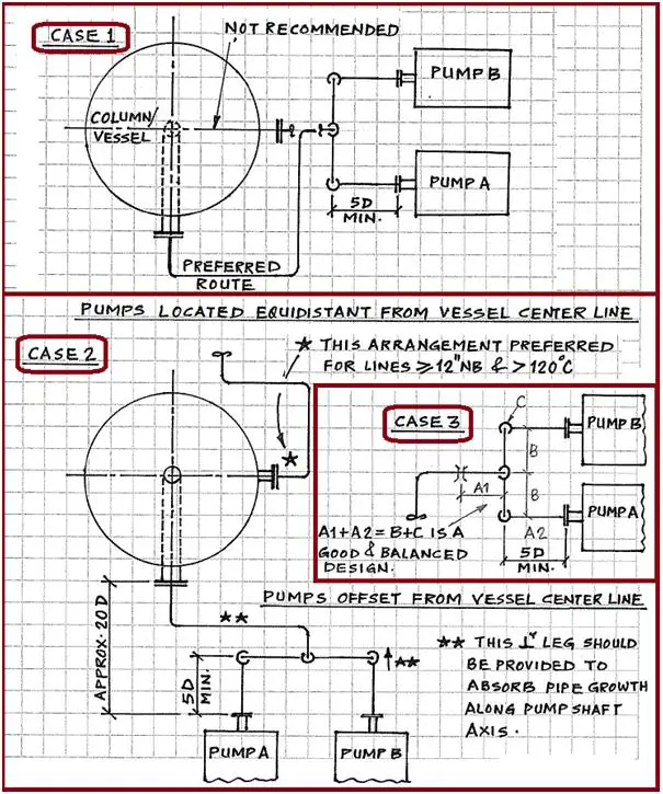
- Case 2 has a column nozzle parallel to the pump axis and this layout is less flexible because thermal growth along the pump axis has to be absorbed by the offset loop.
- Case 3 are preferred arrangement for higher temps and higher suction/discharge pipe sizes.
- Provide min 5D straight run from the first elbow to pump suction.
- First base support shall be adjustable.
- Consider a low-friction slide plate where required.
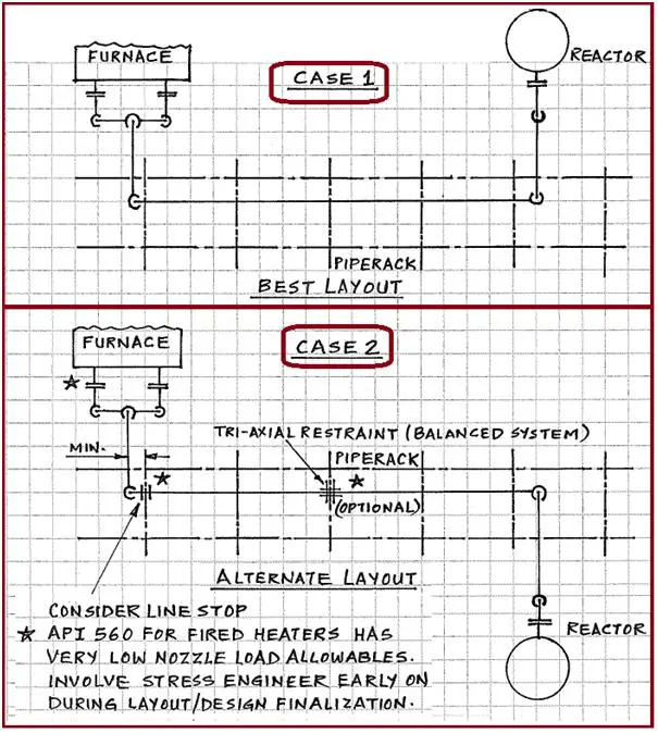
Furnace/Reactor layout and flexibility in piping design when interspaced with a pipe rack. Refer to Fig. 2.
- (Case 1) A common practice is to locate both Furnace & Reactor on the same side of the pipe rack so that the connected line on the rack moves away from the equipment during thermal expansion
- (Case 2) In an alternate layout, the midsection of the line on the rack acts as a pivot allowing the pipe on either side to move away from equipment due to thermal expansion (more loads on nozzles).
Tall Column Piping (Fig. 3)
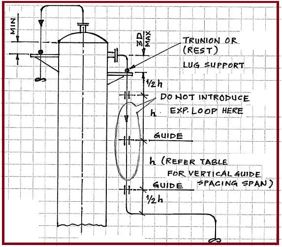
- Considering column expansion is very critical to effective and efficient piping design.
- Column skirt expansion is also critical.
- Use the tables for standard pipe guide spacing for supporting of vertical lines.
- Avoid loop on vertical downcomer alongside the column.
- First support is almost always a “Rest Support”.
Conclusions
- Reduce stress by providing flexibility in the piping system and properly balanced support to ensure uniform distribution of piping loads.
- Remember that pipe moves when hot and movement shall not be restrained by the adjacent pipe.
- Understand that different materials have a different thermal coefficients of linear expansion (i.e. SS expands more than CS).
- Most sustained-case loads (dead loads) in a piping system can be addressed by the designer by use of support span table and guide tables.
- Avoid fitting to fitting routing of lines especially for higher sizes and temps
- Remember that expansion leg in the other direction/plane is good but in third direction/plane is better (3-D loop better than 2-D)
- Piping design owns the ultimate responsibility for effective, economical and efficient design
Few more Resources for you..
Piping Design and Layout
Piping Stress Analysis
Piping Interface
Piping Materials




I have been doing pipe stress analysis using Caesar 2 & changed to Simflex II in 1990 as Simflex is easier to identify input error. It is using Fortran software. I used it until I retired in 2014.
Hope can get one job as Piping designer.
Regards
Sim Chee Chiang
32 years of experience in design
Sichiang518@gmail.com
+6014 5977 900
Malaysia.
pl give me details about metal bellow forming tdchnology. Thanks