
Cathodic Protection is an industrial technique for controlling metallic corrosion. Cathodic protection is commonly used on buried and submerged metallic structures like pipelines, underground storage tanks, locks, subsea equipment, offshore floaters, harbors, and ship hulls. Corrosion is an electrochemical process that operates as an electrical circuit. Corrosion occurs in the anode by oxidation and metal is lost; whereas in the cathode, protection occurs through the reduction reaction. In the cathodic protection technique, the concerned metal is converted into the cathode of the electrochemical corrosion cell to reduce corrosion. In this article, we will explore the basics of cathodic protection principles and industry practices.
Basics of Corrosion
What is Corrosion?
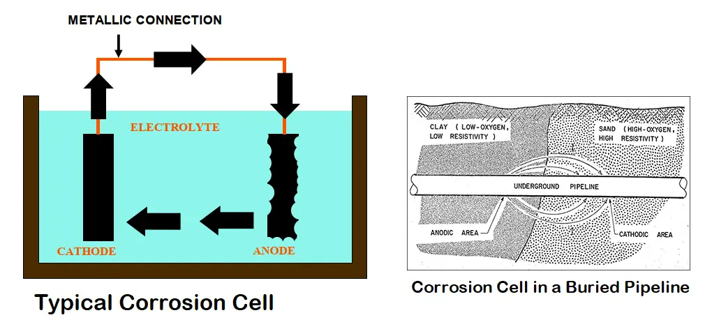
Corrosion can be defined as the degradation of a metal by its electrochemical reaction with a non-metallic matter such as oxygen, sulfur, etc. This occurs by forming an electrical circuit through the exchange of electrons. A corrosion cell consisting of an anode, cathode, electrolyte, and metallic connection between the anode and cathode is formed. So, for corrosion to occur, all the above four parts must be present which creates a closed circuit condition. At the surface of the metal that is exposed to the electrolyte, the electrochemical reaction occurs. The anode corrodes due to an oxidation reaction.
What is an Anode?
This is the most important part of the corrosion cell where corrosion occurs. The anode is defined as the point where the electricity is passed from the metal surface to the electrolyte by chemical means. This chemical reaction is characterized by the metal losing an electron and combining with another element, usually, oxygen is known as the oxidation reaction. In the case of steel, the resulting material is iron oxide popularly known as rust.
What is a Cathode?
The cathode is the second necessary part of the corrosion cell where protection occurs. The cathode can be defined as the point where electricity is passed from the electrolyte to the metal surface by chemical means. This is a reduction reaction characterized by the metal passing electrons to the electrolyte.
Depending upon the electrical potential compared to the other electrode, An electrode can behave either as an anode or as a cathode. This electrical potential difference is the driving electromotive force of the cell and is the voltage difference between the anode and the cathode. The electrode which is more electrically active, or more negative in voltage, undergoes the corrosion, so by definition is the anode. On the other hand, the electrode that is more noble (less negative in potential) passes electrons to the electrolyte (reduction reactions) and by definition is the cathode and does not undergo corrosion.
What is an Electrolyte?
The electrolyte, the third part of the corrosion cell, is the location where ions flow and can be any material in contact with both the anode and the cathode. The electrolyte allows oxidation and reduction reactions to occur and includes the source of atoms required for ion transfer to and from the anode and cathode.
Metallic Path: The final part of the corrosion cell is the metallic path that completes the circuit and allows the electrons to flow. It can be any metal in contact with both the anode and the cathode. For example, In the case of a tank or pipeline, the tank or pipe itself can act as the metallic path.
Effect of Corrosion
One Ampere of current can cause a loss of 9 Kg of Steel in One Year.
Even a small amount of Current discharge, 1 mA can result in 7 holes of ¼” diameter in a 2” steel pipe of standard thickness in 1 year time.
Corrosion can be mitigated by….
- Cathodic Protection
- Selection of Materials
- Coatings
What is Cathodic Protection (CP)?
Cathodic protection is the use of DC Current from an External Source to oppose the discharge of corrosion current from anodic areas of the structure. It minimizes the potential difference between anode and cathode and in turn reduces corrosion. On the application of enough current, the whole pipeline or structure will be at one potential; thus, avoiding the creation of anode and cathode sites.
Principle of Cathodic Protection
The principle of the Cathodic Protection system is determining the anode in a large corrosion cell for making the intended material as cathode overcoming smaller corrosion cells. This can be achieved by any of the following two methods:
Galvanic Cathodic Protection:
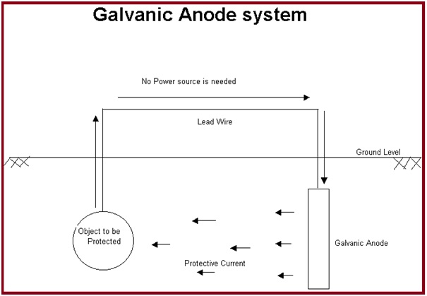
This method first selects a more active metal from the galvanic series. Then the metal is installed in the electrolyte and a metallic path is provided. This method of cathodic protection is called sacrificial cathodic protection, or galvanic cathodic protection. In this method, a galvanically more active metal is installed to act as the anode which sacrifices itself and protects the pipe/structure working as a cathode.
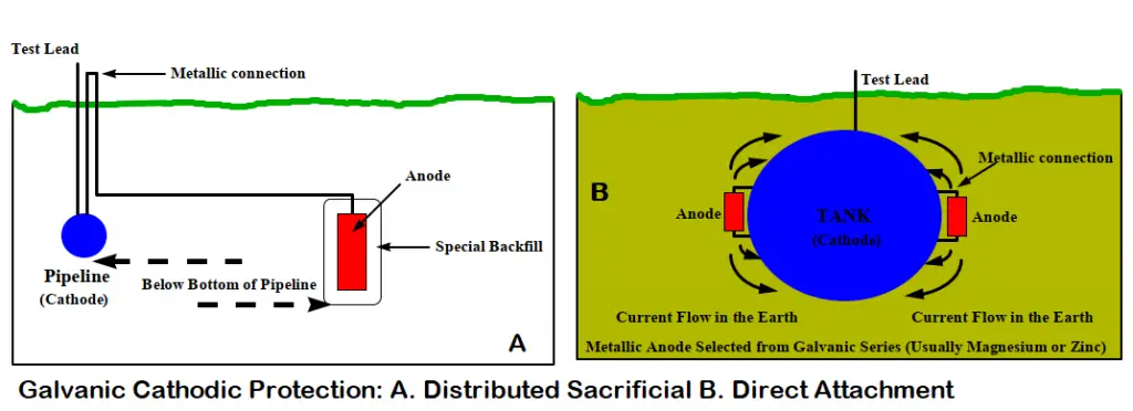
Galvanic cathodic protection systems are fundamentally very simple. The anodes in sacrificial anode cathodic protection systems need to be inspected periodically and must be replaced when consumed. The simplest systems consist of the selection of an anode fabricated from an active metal (normally, zinc, aluminum, or magnesium). Then that sacrificial anode is directly connected to the structure exposing it to the same environment as the structure/ pipeline to be protected.
However, for buried pipelines, the anodes are not directly attached to the structure. They are evenly distributed at a shorter distance from the pipeline. Then the pipeline is connected to the anode using a wire normally through a test station.
Cathodic Protection with Galvanic Anodes:
- Magnesium Anodes
- Zinc Anodes
- Aluminum Anodes
Advantages of Galvanic Anode Cathodic Protection System
- Simple in Installation.
- No External Power Source.
- Very few operation or maintenance requirements.
- No Power Bills.
- Easy to Design.
- No expensive accessories like cables etc.
- Economical for small structures.
Limitations of Galvanic Anode Cathodic Protection System
- Low Driving Voltage.
- Poor performance due to passivation.
- Limited Current. An extremely small current is available in higher-resistivity electrolytes.
- Low life.
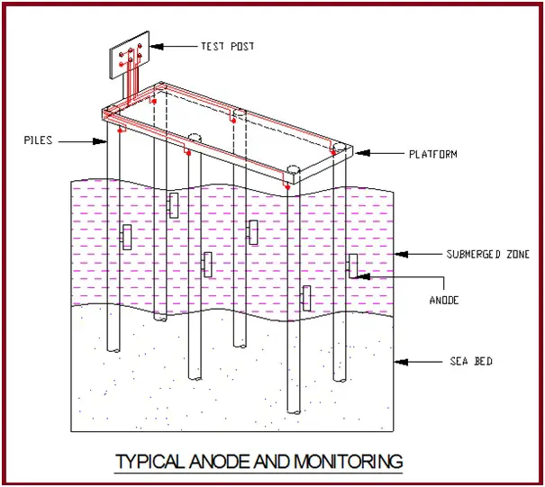
Typical Application of Galvanic anode System
- Small Pipelines with good Coating.
- Harbor Facilities, Steel piles, Jetties, etc.
- Vessels, Tanks, etc.
- Plant facilities and Equipment, Seawater intakes, Screens, Condensers, Heat Exchangers, etc.
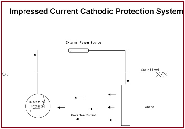
Impressed current cathodic protection:
In the case of impressed current cathodic protection, a source of DC current is installed in the system which provides additional energy to force the current flow from an installed anode to the pipe or structural material making it a cathode. DC source can be a solar cell, rectifier, generator, battery, or some other DC power.
The anode material is selected considering the cost and weight loss per ampere year of current. Graphite, high silicon cast iron (HSCI), platinum, or mixed metal oxide are used as anodes for impressed current cathodic protection systems as they are slowly consumed. The anodes should be periodically inspected and replaced if consumed.
Cathodic Protection with Impressed current Anodes:
- High silicon chromium cast iron Anodes
- Mixed Metal Oxide Anodes
- Graphite Anodes
Advantages of Impressed Current Cathodic Protection System
- Current and Voltage can be varied.
- Can be used in almost any resistivity Environment.
- Can be designed for remote monitoring and control.
- Can be designed for the measurement of Instant OFF / ON.
- No limitation on driving Voltage.
- Economically feasible to replace the anode system when required.
- The system is extremely flexible.
Limitations of Impressed Current Cathodic Protection Systems
- Regular monitoring and maintenance required
- Requires Main supply or another source of electric Power
- Interference Problems must be considered.
- Relatively large chance of premature failure or breakdown.
Theory of Cathodic Protection
- Steel in soil/water Anodic
- Earth / Sea water Cathodic
As a result:- Steel loses electrons and hence corrosion
To reverse the above:
- Make steel Cathodic
- Seawater / Earth Anodic
And this is the theory of cathodic protection where the intended material is converted into a cathode.
How does Cathodic Protection Work?
Direct Current is forced to flow from an external source to the Structure. When the flow of this current is so adjusted to overpower corrosion current discharging from all anodic areas thereby providing complete Protection.
Criteria for Cathodic Protection
Steel in Soil: Pipe to Soil potential must be between –0.85 V to -1.2 V with respect to Cu/CuSo4 Reference Electrode.
Steel in Water: Pipe to Electrolyte potential must be between –0.8V to –1.10V with respect to Ag/AgCl Reference Electrode.
BASIS FOR CURRENT DENSITY….
SOIL RESISTIVITY
- >1000 ohm-cm 10 mA/m2
- 100-1000 ohm-cm 20 mA/m2
- <100 ohm-cm 35 mA/m2
WATER RESISTIVITY
- >150 ohm-cm 50 mA/m2
- 50-150 ohm-cm 75 mA/m2
- <50 ohm-cm 110 mA/m2
Cathodic Protection System Design
Prior to deciding the type of cathodic protection system and its design, certain preliminary data must be collected.
Data required for deciding a Cathodic Protection System
The following data are required for deciding on a cathodic protection system
- Details of Structural Dimensions and drawings
- Surface Coating Scheme
- Details of Soil Strata / Terrain
- Presence of Foreign Metallic Structures.
- Details of cased crossings
- History of corrosive areas
- Stray current conditions
- Operating Temperature
- Availability of AC Power
- Corrosion history of structures in the area
- Electrolyte resistivity and pH survey report to understand corrosion rate
Planning a Cathodic Protection System
Factors that govern the Cathodic Protection System Design:
- Choice of Cathodic Protection system
- Amount of Total Current to achieve Cathodic Protection
- No of Cathodic Protection Installations
- Spacing between them &
- Current Output of each Installation
- Type of anodes and ground bed configuration
- Any special conditions at certain locations needing modification of the general CP Plan
- Location of CP Test station.
Selection of a Cathodic Protection System
The size of the structure, soil resistivity, and past corrosion history dictate the selection of a cathodic protection system. A current requirement test to protect the structure is performed before the selection. In general, when the soil resistivity is low (< 5000 ohm-centimeters) and the current density requirement is low, a sacrificial anode cathodic protection system is selected. However, for large structures with larger current requirements, a properly maintained impressed current system is used.
Cathodic Protection System Design Sequence
The following flowchart provides the design sequence for the cathodic protection system design sequences.
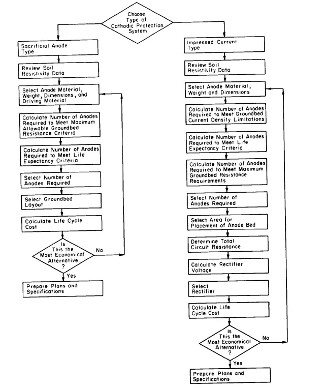
The below-mentioned steps are usually followed while designing a sacrificial anode cathodic protection system design:
- Review soil resistivity
- Select anode: For extremely corrosive soil (<2000 ohm-centimeters), Zinc is used. Otherwise, magnesium is used.
- Calculating the net driving potential for anodes.
- Finding the number of anodes needed to meet ground-bed resistance limitations.
- Estimating the number of anodes for the system’s life expectancy.
- Selecting the number of anodes to be used
- Selecting the ground-bed layout
- Calculation of the life-cycle cost for a proposed design.
- Preparing plans and specifications
Similarly, the below-mentioned steps are followed for designing an impressive current cathodic protection system design:
- Review soil resistivity
- Review current requirement test
- Select anode: Anode selection is based on cost consideration.
- Estimating the number of anodes needed to satisfy the manufacturer’s current density limitations
- Calculate the number of anodes needed to meet the design life requirements.
- Calculate the number of anodes needed to meet maximum anode ground-bed resistance requirements.
- A select number of anodes are to be used.
- Select the area for placement of the anode bed.
- Determine total circuit resistance.
- Calculate anode ground-bed resistance.
- Calculate ground-bed header cable resistance.
- Calculate structure-to-electrolyte resistance.
- Calculate total circuit resistance.
- Calculate rectifier voltage.
- Select a rectifier.
- Calculate system cost.
- Prepare plans and specifications.
Why do we need Cathodic Protection in Plants
- Initial Investment for Petrochemical complexes, Fertilizer Plants, and Refineries are very high.
- The corrosion problems are not detected until some leak appears.
- Leakages can be extremely disastrous causing fatal accidents and great financial loss.
- Increases maintenance cost of repairs of leakages.
- The corrosion problem can also cause plants to shut down thereby losing production.
- Cathodic Protection can be installed at the time of the erection of the plant at a very low cost.
- The CP cost could be 5-6 times if it is installed after completion of the project as it involves a lot of excavation and restoration of structures.
Complexities of Plant Cathodic Protection
- Scattered Underground Pipelines
- -Pipes in Parallel
- -Bifurcations
- -Closely grouped network
- Different pipes could be of different materials and coatings.
- The area of influence shall vary from pipe to pipe.
- Heavy underground civil structure reinforcements
- Earthing network.
- Tank Bottoms
Corrosion Control for Above Grade Storage Tanks using CP system
- The Tank bottom in contact with soil undergoes corrosion. This could lead to leakage, loss of product, and cause environmental hazards.
- It is much simpler and economical to install a CP system during the construction stage.
Cathodic Protection for Pipelines
The main data required for deciding a Cathodic Protection System for pipelines are
- Details of Structure Dimensions
- Surface Coating Scheme
- Details of Soil Strata / Terrain
- Presence of Foreign Metallic Structures.
- Details of cased crossings
- History of corrosive areas
- Stray current conditions
- Operating Temperature
- Availability of AC Power
Equipment used for Cathodic Protection System
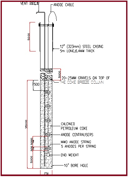
Anodes
- MMO Anodes
- Silicon Iron Anodes
- Graphite Anodes
The anodes are installed in deep well borehole ground beds.
Solar Generators
In corrosion Protection Stations where the input power is not available, Solar generators are used to power the CP system.
Anode Junction Box (AJB)
The anode junction boxes are used to distribute the DC power from the T/R unit to the anodes at each CP station. The anode tail cables and the positive header (from T/R) are terminated inside the AJB. One circuit with suitably rated shunts for monitoring the current output of the anode string.
Negative Distribution Box (NDB)
The negative header cable (from T/R) and negative drain cable from the pipeline are terminated inside the NDB at each CP station. Each circuit shall have a variable resistor to control the current and suitably rated shunt to monitor the current.
Solid State Polarization Cell
Pipeline to be earthed at all overhead powerline crossings where the voltage is greater than 100 kV. Connected across the pipeline and the system earthing. Prevents the CP current drain from the structure to the system earthing. Shunts all fault currents and induced currents to the earth.
Surge Diverters
Surge Diverters are used across Isolating Joints Facilities. Provides surge protection to Isolating Joints in case of a lightning strike or other faults.
Monitoring of the Corrosion Protection System
For routine maintenance and monitoring of the effectiveness of the CP system, the following test facilities are provided along the pipeline.
- POTENTIAL MEASUREMENT FACILITY: For measurement of the pipe-to-soil potential with respect to a portable reference cell. These facilities are provided at a regular interval of one facility every two kilometers
- DRAIN POINT TEST FACILITY: At each CP station a drain point test facility is provided. Two permanent reference cells, two polarization coupons, and one corrosometer probe are used to measure the pipe-to-soil potential with respect to a permanent buried Cu/CuSO4 reference cell and the instant OFF potential from a buried coupon. Corrosometer allows monitoring of the corrosion rate and thereby the performance of the system. Permanent Reference cells are used to feed data for the SCADA system.
- FOREIGN SERVICE CROSSING/PARALLEL FACILITY: To carry out interference testing at foreign pipeline crossing or foreign pipelines running parallel to SGP. To facilitate the mitigation of Interference effects
Cathodic Protection System Monitoring Frequency
Economic and safety considerations require close supervision and maintenance of all cathodic protection systems. Monitoring can be divided into three categories:
- Monthly Monitoring
- Quarterly Monitoring
- Annual Monitoring
Monthly Monitoring:
- Recording drain point potentials
- Ground bed resistance
- Anode current output
- T/R output and T/R settings
- Solar output settings
Quarterly Monitoring:
- Recording Structure to Electrolyte Potential at the measurement location. (Only ON potentials are to be recorded)
- Bonding Currents to be measured.
- Isolation joints are to be tested using the Swing Test.
- Reports to be generated.
- Solar output settings
Close Interval Potential (CIP) and Direct Current Voltage Gradient (DCVG) Surveys
- It is recommended that a Close Interval Potential Survey should be conducted within one year after commissioning the Corrosion Protection system. This should be repeated once every three to five years.
- Based on the CIPS data, the DCVG survey should be conducted immediately at sites where under protection has been observed during the CIP survey. It is also recommended that a DCVG survey is conducted for the entire pipeline once every three to five years.
So, we can conclude that cathodic protection is a very useful and widely used method of steel protection. However, this method is costly and requires periodic maintenance and replacement. Click to know more about the Design of Cathodic Protection for Duplex Stainless Steel (DSS) Pipeline
How much our reading True Potential Power(mv) CP Criteria in Minimum & Maximum after
conducting “ON / OFF” potential survey.
Considering there is a present of Sulfur Reducing Bacteria.
I want to get job opportunity as Corrosion Engineer , please inform me if any opportunity
thank you
kind regards
Hi Mr Kumar,
I am curios about the Criteria for Cathodic Protection
Steel in Soil: Pipe to Soil potential must be between –0.85 V to -1.2 V with respect to Cu/CuSo4 Reference Electrode. I would like to know which standard or code of practices states these values.
Thanks in advance it will help my research.
Have a nice day!
I am working in the ships, ask during ships moving CP on and during anchoring can we keep CP on power the anchor chain petting the earth.
PLS advice.
I have one year experience in cathodic protection inspection, i was working with SNGPL a natural gas company in pakistan, i am also with 3year mechanical diploma. Iam curious about finding job in cathodic protection inspection i have vst knowldge about inspection of cp station and pipeline protection,mow iam here in abu dhabi looking for a job in my own forld but still not finding the way where can i apply.
Dear sir,
Please tell me
Are both these stations the part of every ICCP system ?
1- Unidirectional drainage stations
2-Negative drainage stations
need urgent guide please
Is cathodic protection job is harmful for the workers
Hi sir,
Good day.
I am working in 300 MW TPP in Zambia country. Here we have heavy underground pipelines for cooling water circulation. we have frequent challenges of pipeline holes and water leak from the holes results unit shutdown if leak occurred at generator cooling water pipes. can you suggest the better way to prevent this corrosion problem. unit is constructed in the year of 2015. Soil condition is Sulphur content and coal mines area.
Thanks, and regards
Vinod kumar.