
The article is about the Design of Cathodic Protection for Duplex stainless steel. The design includes many parameters like
- Current density.
- Coating breakdown factors.
- Mass of anode.
- Current output and many others.
The article mainly involves the Cathodic Protection design for the Duplex stainless steel pipeline. The Cathodic Protection design is also done for the Carbon steel pipeline(48” diameter with Al anode) and Duplex stainless steel( 24 “ diameter with Zn anode) and is compared and analyzed with the main objective, Duplex stainless steel pipeline (48” diameter with Al anode). Finally, the designs are interpreted, compared, and analyzed.
What is Cathodic Protection?
Cathodic Protection is defined as
- “an electrochemical protection by decreasing the corrosion potential to a level at which the corrosion rate of the metal is significantly reduced” (ISO 8044).
- “a technique to reduce corrosion of a metal surface by making that surface the cathode of an electrochemical cell” (NACE RP0176).
Need for Cathodic Protection
Cathodic protection is one of the important factors in the performance of the pipeline carrying crude or petroleum products. If the pipeline has to be operated until its designed life with the least maintenance activities, Cathodic Protection is the best way to adapt. The pipeline with minimum care can lead to leaks, ruptures, etc, which affects the supply and other contract terms, which results in loss of crude or product, demand, money, time, etc.
The motto behind cathodic Protection
The main motto behind Cathodic protection is “prevention is better than cure”. It’s better to design and install perfect cathodic protection rather than opting for complex and unpredictable maintenance schedules.
Duplex Stainless Steel (DSS)
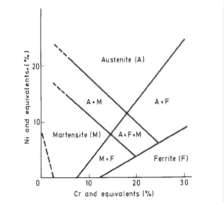
- The name itself implies that the steel is of a two-phase structure.
- The figure-1 shows the structure of Duplex steel.
- Commonly considered Duplex stainless steel is Austenite and Ferrite A.F region.
The different forms of Duplex stainless steel available are shown in Fig. 2. In this article DSS, 22Cr 5.5 Ni 3 Mo 0.18N is considered.
| C | Cr | Ni | Mo | Cu | W | N |
| 0.02 | 18.5 | 4.9 | 2.7 | 0.07 | ||
| 0.05 | 22.5 | 8 | 2.4 | 1.5 | ||
| 0.02 | 22 | 5.5 | 3 | 0.18 | ||
| 0.02 | 25 | 5.5 | 3 | 1.8 | 0.18 | |
| 0.02 | 25 | 7 | 3.5 | 0.8 | 0.8 | 0.22 |
Advantages of Duplex Stainless Steel
The main advantages of Duplex Stainless Steel are
- High strength.
- A cost-effective alternative to austenitic stainless steel.
- High resistance to pitting, and crevice corrosion resistance.
- High resistance to stress corrosion cracking, corrosion fatigue, and erosion,
- Good sulfide stress corrosion resistance, except at high
- Low thermal expansion and higher heat conductivity than austenitic steels,
- Good workability and weldability,
- High energy absorption.
- Mainly used as subsea material.
Drawbacks of DSS
However, there are a few drawbacks like
- Cost factor.
- Fails at higher temperatures, which may result in Hydrogen Induced Stress Corrosion Cracking(HISC).
- Need expertise in welding. Otherwise, it may lead to HISC, crevice corrosion, etc.
Design of Cathodic Protection
Basic inputs for cathodic protection-
- Pipeline diameter for Duplex with Al anodes, D = 48”.
- Length of the pipeline, LP = 71.650km.
- Pipeline joint length, Lj = 12m,
- Design life, T = 40 years,
- Design temperature, t =45 0 c.
- Corrosion coating thickness, tc = 5mm.
- Mean Coating breakdown factor, fcm= 0.05.
- Final Coating breakdown factor, fcf = 0.11.
- The gap between half-shells, G = 100mm
- Anode spacing, S = 4 joints.
- Electrochemical resistivity, for seawater, ξ = 20-ohm cm.
- Anode utilization factor, U = 0.8.
- Mean current density, i cm or CA = 80 mA/m2
- Final current densities, i cm or CF =150 mA/m2
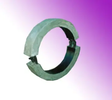
Bracelet type of anode (Fig. 3)
For Duplex stainless steel pipelines, the other parameters considered are:
- Al Anode material density, ρ= 2700 kg/m3.
- Electrochemical efficiency,ε= 1825 A-hr/kg.
- Protective potential, VP = – 500V.
- Closed circuit anode potential, VA = -1050 mV.
Design calculations for cathodic protection
Diameter of the anode:
Di=D+2tc=1219+(2*5)=1229mm.
Spacing
SL = S* Lj=48mm.
Number of anodes,
N = LP / SL =1493.
The net mass of each anode
MA= ᴨ/4((D+2tc)2– Di2)-2GtA)LAρ=196.2 kg
Total anode mass
M=NMA= 1493*196.2=292926.6kg.
Mean current output
IMC= εUM/T= 1219.692A
Mean current required, IMR
= CAbAᴨDLF=80* 0.05*ᴨ* 1219*71650= 1097.56A.
Final surface area per anode,
AF=ᴨ[Di+2(1-U)tA-2G]LA
=ᴨ[1229+2(1-0.8)110-2*100]150= = 0.572m2 .
Resistance of each anode,
RA=0.315ξ/√A=0.083ohm.
Final current output
IFC= N[VF – VA]/RA
= 9893.373A.
The final current required,
I FR = CFbFᴨ D LF
= 4527.451A.
The below two parameters will say whether the whole calculation for CP is feasible or not.
- Mass requirement = IMC/IMR=692/1097.564= =1.11>1
- Final output current = IFC/IFR = 9893.373/4527.451 = 2.19>1.
The calculations are also done for
- Carbon steel pipeline with Al anode,48” dia.
- Duplex stainless steel pipeline with Al anode,48” dia.
- Duplex stainless steel pipeline with Zn anode,24” dia.
Results
- From the calculations, it can be inferred that the Duplex stainless steel requires less amount of anodic material.
- A graph (Fig. 4) is shown for the Mass of the anode (kg) vs current output(A).
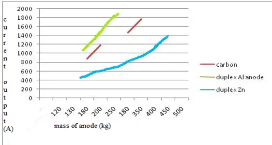
- It can be inferred that the Duplex with less amount of anodic material can give high current output, in the case of Al anode.
- In the case of Zn anode for Duplex stainless steel, more anodic material is needed for maintaining the current output, because the consumption rate of Zn is more.
Consumption Rate (Fig. 5)
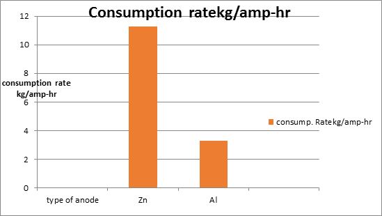
- This graph shows the consumption rate of anodic materials. Zn anode consumption rate is higher than Al. As a result, more amount of material is needed for meeting the current demand when compared to Al.
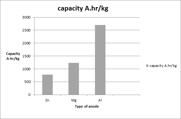
- The aluminum anode is much preferable because of its high capacity compared to other anodic materials. The graph below discusses the
Capacities of anodic materials (Fig. 6):
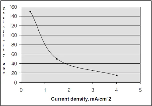
Resistivity vs Current density
From the graph below (Fig. 7), it can be inferred that the current may decrease along with the increase in resistivity.
Conclusion
- The focus is projected on the CP design for DSS and carbon steel with the application of different anodes. The factors like the mass of anode current output etc. are concerned for the performance analysis of CP with different anodes.
- It may be interpreted from the article that Duplex stainless steels with Al as anodes are best suitable for offshore applications.
Recommendations
- Hg-free Aluminium sacrificial anodes are recommended for the best performance of CP in subsea pipelines.
- Duplex stainless steels are best recommended for subsea pipelines because they are having good mechanical strength, high pitting corrosion, and HISC-resistant properties at normal temperatures.
- Highly skilled welding to avoid flaws in the weld. The flaws may result in HISC at the welded portion of the pipeline.
- Galvalum-III is the best-recommended anode certified by the DNV RP 401. It can even protect the hot oil pipelines which normal anodes may not do. These anodes are not susceptible to inter angular corrosion and can be used in place of Zn anodes.
Few more Pipeline related useful Resources for You..
Underground Piping Stress Analysis Procedure using Caesar II
Comparison between Piping and Pipeline Engineering
A Presentation on Pipelines – Material Selection in Oil & Gas Industry
Corrosion Protection for Offshore Pipelines
Start up and Commissioning of the Pipeline: An Article
DESIGN OF CATHODIC PROTECTION FOR DUPLEX STAINLESS STEEL (DSS) PIPELINE
AN ARTICLE ON MICRO TUNNELING FOR PIPELINE INSTALLATION
A short presentation on: OFFSHORE PIPELINE SYSTEMS: Part 1
Factors Affecting Line Sizing of Piping or Pipeline Systems
During offshore pipeline CP continuous proximity inspection we obtain, Contact CP Value (mV) , Field Gradient (μV/cm),
kindly I need example on calculation the Current Output (mA), and Remaining Life (Years)
We know the optimum range of voltage providing Cathodic Protection to Carbon Steel Pipelines or other CS underground structures is starting from -0.85 V to around -1.2 V or even lower to -1.4 V. Is this is correct? Also is this same range of Voltage applicable for Duplex Stainless Steel (DSS) Pipelines?
TY great article.
I have a question we install roof safety systems inland and at the coast.
I seek a sacrificial anode to protect my products when installed in the spray zone at the coast (+- 80m from the shore). We use both MS355 coated with epoxy and 3CR12 coated with epoxy.
What size washer would be suitable to prevent this corrosion?
Assuming Zinc would be my best bet? Our largest plate is 515mm x 320mm x 5mm thick
Kind regards