Several failures in buried piping and pipeline systems over the years forced EPC companies to investigate the stresses the system is experiencing. So, in recent times, stress analysis of underground piping and pipeline systems are made compulsory. In most cases, buried analysis is followed for pipelines as the maximum part of pipeline systems are underground. And the analysis is governed by ASME B31.4 or B31.8 Codes.
In my earlier article on Buried Piping, I explained the theoretical background of stress analysis of underground piping. Click here to visit that article. In this article, I will explain the steps required to follow for modeling and analyzing the pipes in Caesar II.
Inputs Required for Buried Piping Stress Analysis
Like all other piping systems, you need to model the piping in Caesar II initially following the same conventional method. So you need the following inputs:
- Piping isometrics or GA drawings with dimensions.
- Pipe parameters like temperature, pressure, material, diameter, thickness, corrosion allowance, fluid density, etc.
- Additionally, you need the following soil parameters from the civil department (geo-technology department) for the creation of the soil model using the Basic Caesar II soil model.
- Friction Co-efficient
- Soil Density
- Buried depth to the Top of the Pipe and
- Friction Angle
- Equipment/Valve GA drawings as per application.
Modeling the piping/pipeline system in Caesar II
Follow the below-mentioned steps:
Model the piping system from isometrics/GA drawings using the pipe parameters.
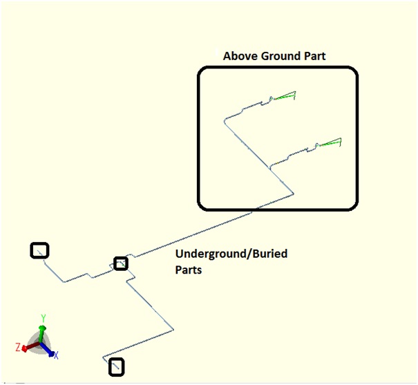
Normally some parts of the system will be above ground and some parts will be buried. Let’s take an example of a typical system for easy understanding. Refer to Fig 1. The stress system consists of a 24-inch CS pipe connected to a tank. The parts inside the rectangle are above ground and the remaining parts are underground.
Create a distinct node at all the junction points of underground and above-ground piping.
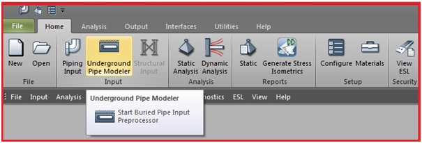
After you complete your model, save it, close it, and then enter the buried model by clicking the Underground Pipe modeler button as shown in Fig. 2.
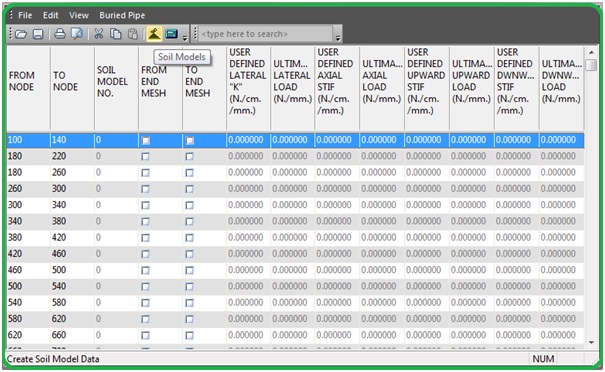
Once you click on the underground pipe modeler the following screen (Fig. 3) will open. You will find all your input node numbers listed there.
Now your task is to create the soil model and input data received from civil. On clicking the Soil Models button (Highlighted in Fig.3) you will get the window where you have to enter the data. You have two options to select as soil model type, Americal Lifelines alliance, and Caesar II Basic Model. We will use the Caesar II basic model for this article.
So select the Caesar II Basic model. The modeler uses the values that you define to compute axial, lateral, upward, and downward stiffnesses, along with ultimate loads. Each set of soil properties is identified by a unique soil model number, starting with the number 2. The soil model number is used in the buried element descriptions to tell CAESAR II in what type of soil the pipe is buried. You can enter up to 15 different soil model numbers in any one buried pipe job.
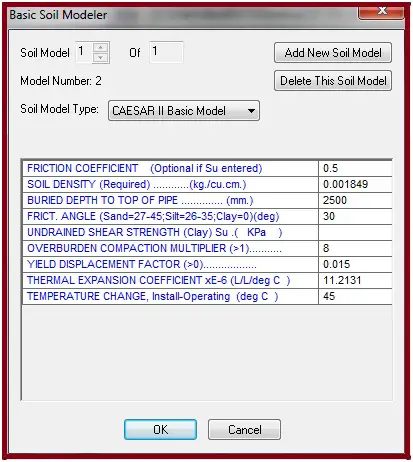
Input the parameters as shown in Fig. 4. If you require to add more soil models simply click on add new soil model. The overburden compaction factor, Yield displacement factor, and thermal expansion coefficient will automatically be filled by default. You need to input all other fields. However, defining a value for Temperature change is optional. If entered the thermal strain is used to compute the theoretical “virtual anchor length”. Leave an undrained shear strength field blank. After all, data has been entered click on the ok button.
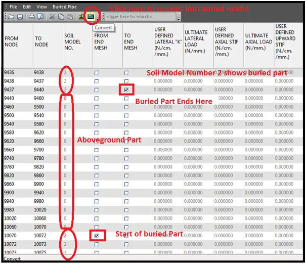
Now inform Caesar II about the underground and above-ground parts by selecting the nodes and defining the proper soil model number. If you enter 0 as a soil model number, the element is not buried. If you enter 1, then specify the buried soil stiffness’s per length basis in columns 6 through 13. (preferably do not use 1). If you enter a number greater than 1, the software points to a CAESAR II soil restraint model generated using the equations outlined in Soil Models of Caesar II. Refer to Fig. 5 for an example. After all the aboveground and underground parts along with proper soil, a model number is defined click on the convert button and Caesar II will create the underground model.
When the underground model conversion is over you will get the buried model. By default, Caesar II appends the name of the job with the letter B. For example, if the original job is named System1, the software saves the second input file with the name System1B. If the default name is not appropriate, you can rename the buried job.
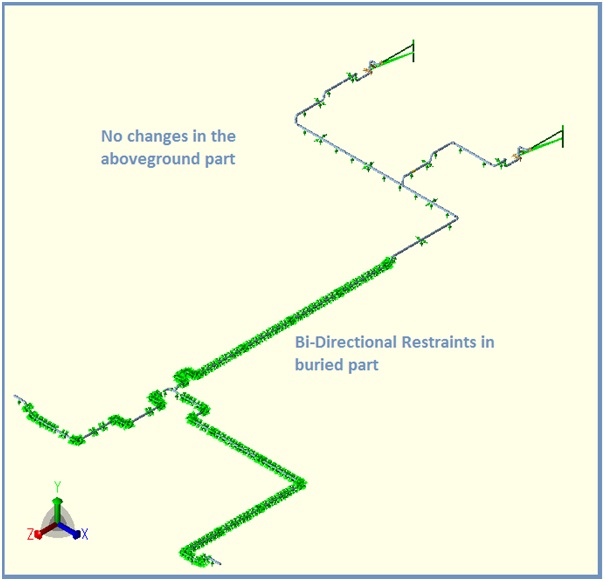
In the buried part, Caesar II models bi-linear restraints with stiffness values which the software calculates while converting into the buried model. Refer to Fig. 6 to check the buried model of the system shown in Fig.1. These stiffness values depend on the distance between the nodes.
Now open the file (original file appended by B) and perform static analysis in the same conventional way and qualify the system from code requirements.
Few Important points to keep in mind
- Typical values of friction angle are as follows:
- Clay – 0
- Silt – 26-25
- Sand – 27-45
- Typical friction coefficient values are:
- Silt – 0.4
- Sand – 0.5
- Gravel – 0.6
- Clay – 0.6
The default value of the overburden compaction multiplier is 8. However, this number can be reduced depending on the degree of compaction of the backfill. Backfill efficiency can be approximated using the proctor number, defined in most soils textbooks. Standard practice is to multiply the proctor number by 8 and uses the result as the compaction multiplier.
After entering data in the soil model when you click ok, the Caesar II software saves the soil data in a file with the extension SOI.
During the process of creating the buried model, the modeler removes any restraints in the buried section. Any additional restraints in the buried section can be entered into the resulting buried model. The buried job, if it exists, is overwritten by the successful generation of a buried pipe model. It is the buried job that is eventually run to compute displacements and stresses.
Caesar II removes the density (pipe density, fluid density, insulation density, etc.) from the buried part model while converting it into the buried model.
Additional Considerations for Buried Piping Systems
There are a few additional considerations that the analysis by Caesar II does not ensure. Caesar II stress analysis only ensures the system stresses with regard to temperature change and piping weight and pressure. Hence, those need to be considered while designing the buried piping as listed below:
- Buoyancy Consideration
- Road Traffic Consideration
- Piping Ovality check etc
Online Course for Buried/Underground Pipe Stress Analysis
If you wish to attend an online course on buried/underground pipe and pipeline stress analysis with a practical case study then click here to join the course
Few more Resources for You..
Video Tutorial of Buried Piping Stress Analysis using Start-Prof
Basics for Stress Analysis of Underground Piping using Caesar II
What if Piping Continuation is Unknown? Part 2. Underground Piping
A short presentation on Various Analysis methods for Underground Piping Using Caesar II
Piping Stress Analysis Basics
Piping Design and Layout Basics

very nice
can upload analysis for steam out condition
It’s good attitute and excellant sharing of knowledge.
Thanks for nice data.
Can you explain how to the ‘code stress over’ for underground piping? (I think apply thrust block, change route…)
Nice short detailed write up
Hey! This post couldn’t be written any better! Reading through this post reminds me of my good old room mate! He always kept talking about this. I will forward this article to him. Fairly certain he will have a good read. Thanks for sharing!
Thank you for sharing your valuable knowledge.
what can we do when the piping is vertically entering in the ground?
the distance of piping is for horizontal piping.
Good
Hi, how you model culvert/sleeve for buried pipe?