
Once the three-dimensional (3D) model has been established in piping design software like PDS, PDMS, or SP3D, Piping Designers/Engineers need to convey that information to the yard for fabrication and the site for Construction. The transferred information must be sufficient for the fabricator with the vision of what is to be fabricated and how the piping should be connected with other elements, with exact dimensions and a complete build/Bill of materials (BOM). This is where Piping Isometric Drawings play a magnificent role. So piping isometrics are directly used for the following situations:
- For Construction Services
- For marking up deviation during site modifications/ as-builting.
- For reference as Stress Analysis model built-up and the final stress markup for updating stress requirements.
Uses of Piping Isometrics
Isometric Drawings for Piping help to calculate many parameters required during project execution like:
- Inch Meter can be estimated as the Length of pipe (in meters) x Size of pipe ( in inches).
- Inch Dia is calculated as the Size of the Pipe joint ( in inch) x No, of Joints.
- Pipe Weight is calculated as π x diameter of the pipe (in m) x length (in m) x thickness (in mm) x density of pipe material. The density of CS = 7.85 g/cm3.
- The volume of Water required for hydro testing is estimated as π x {Pipe ID (in meter)}² x Length of Pipe.
- Insulation Area (in m²) can be found as [π(Pipe OD+ insulation thickness)] (all in meter) x Length of Pipe (in meter).
Additionally, isometric piping drawings serve the following purposes:
- Maintenance teams use isometric drawings to understand the existing piping layout and plan for repairs or modifications.
- Fabricators and construction teams use these drawings to cut, assemble, and install piping systems accurately.
- Engineers and designers use isometric drawings to plan and design piping systems, ensuring all components fit together correctly and meet design specifications.
What is Piping Isometric Drawing?
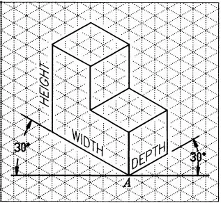
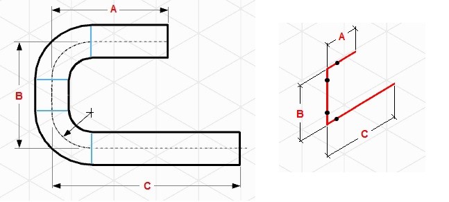
By definition, Isometric drawings are a pictorial representation that combines height-width-depth/length into a single view with 30 degrees from its horizontal plane as shown in the attached image.
It is a detailed 3D representation of a piping system that allows for visualization and understanding of the system’s layout, components, and flow paths.
Features of Piping Isometric Drawing
An isometric Drawing is a two-dimensional (2D) drawing that represents the 3D piping system. Sometimes piping isometrics are also known as pipe fitting isometric drawings. The important features are
- It is not drawn to the scale, but it is proportionate with the exact dimensions represented.
- Pipes are drawn with a single line irrespective of the line sizes, as well as the other configurations such as reducers, flanges, and valves.
- Pipes are shown in the same size. The actual sizes are notified in the Bill of Material, tagging, call-out, or notes.
- A piping isometric drawing provides all the required information like:
- Pipe Line Number
- Continuation isometric number
- Flow direction
- Piping dimensions
- Piping joint types, weld types
- Flange and valve types
- Equipment connection details
- Piping and Component descriptions with size, quantity, and material codes
- Precise dimensions for all components and the distances between them are provided.
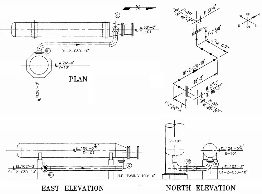
Piping Isometric drawings are popular because of their simplicity, yet efficient in conveying complex information. The following figure gives an example of how one Isometric drawing can represent three orthographic drawings. That is just a simple piping drawing. Imagine complex design and yet orthographic drawings are used for construction, that is really a headache.
In earlier days, Isometric drawings were hand-drawn. With the innovation and advancement of the digital age, isometrics are drawn by AutoCAD/Microstation software. In recent days, 3D models could automatically extract the Isometric with a single click of a mouse.
Creating a piping isometric drawing template can help standardize the process and make it easier to produce consistent and accurate drawings. However, the isometric drawing template may differ from one organization to another.
How to Read Piping Isometric Drawings?
1. Imagine that the piping system is built in a box. This basic imagination is required for the piping to have an offset. So, it will help you to imagine, how the piping configuration will look as it travels.
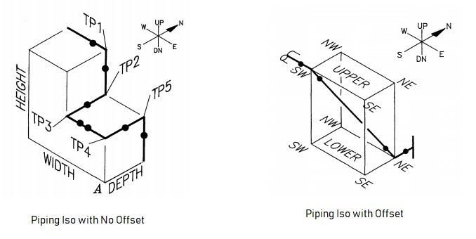
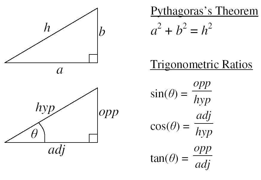
2. Offset happens when the pipe turns to any angle other than 90 degrees or to accommodate the odd nozzle’s location or tie-in point connections. A popular use is a 45-degree elbow and this is used extensively in piping design. In such cases, piping design may land on Northeast, Southeast, Northwest, or Southwest axes. In order to check the dimension of pipe length with offset, common Pythagoras’s theorem and Trigonometric rule can be used. A sample calculation is shown below as a reference-
Length Calculation in Piping Isometric Drawing Examples
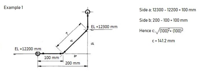
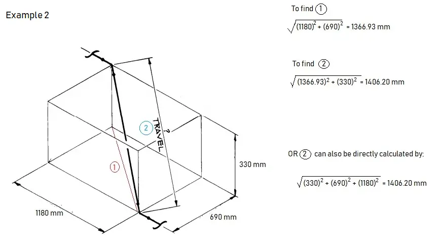
Example of offsets in Piping Isometric Drawing
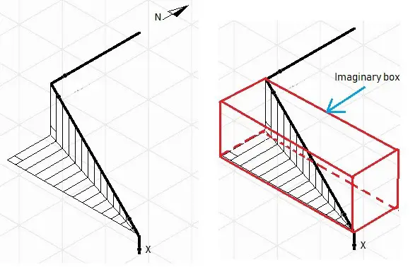
If you happen to have difficulties reading the offset, try to draw the imaginary box. It could help you have a better understanding of which axes the pipe travels and how the piping should look like. In the example given, take the flow from ‘x’, the pipe goes up; then up-northwest; then north. As you get along with Iso a lot, things will come naturally.
Piping Isometric Drawing Rolling:
In piping isometric drawings, “rolling” refers to the change in direction of a pipe in more than one plane. A “roll” occurs when a pipe changes direction both horizontally and vertically simultaneously. This is a common occurrence in complex piping systems where space constraints or other design considerations necessitate such a change. Sometimes, the 3D offset is also known as rolling in the piping isometric drawing.
3. A North arrow is provided in all piping isometrics to inform the location of the piping system in the piping/ general arrangement drawing.
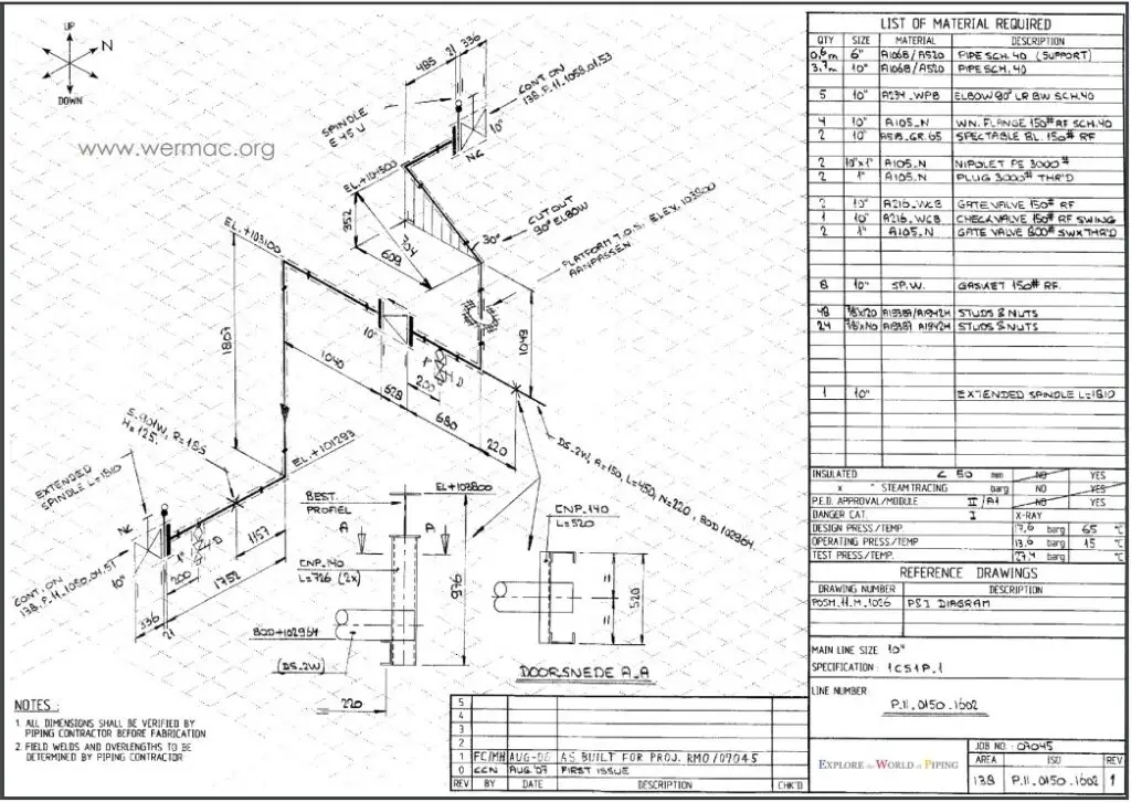
4. The piping isometrics also has coordinates & elevation detailed information to verify the exact length of the pipe in horizontal and vertical axes respectively. The dimensions in Isometric drawings are measured from the pipe centreline and not from the outer diameter of the pipe (refer to the image attached below for reference).
With the advancement of technology, there could be minimum or even zero possibilities that the North arrow, coordinates, and elevation in Isometric would differ from the piping arrangement; hence the dimensions and MTO should match exactly if the source 3D model is the same.
However, It is always better to check and verify as there could be some issues with the modeling itself that may cause discrepancies in material and quantity. For example, if double piping is modeled by mistake, it will read the double quantity of material.
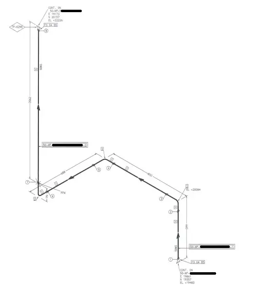
5. Isometric pipe drawings also inform which piping should be constructed at the fabrication shop and which should be assembled at the construction/platform field itself. The complete piping system is separated into pieces that are transported to the site for erection. These small pipe pieces are termed piping spools. One sheet of Isometric drawing normally has few spools.
Every weld that is assembled between spools at the construction site is termed a field weld (FW). There is one more type of weld that is known as field-fit weld (FFW). This FFW is defined by the designer if he/she could foresee that the spool might require some adjustment before the final fit-up, so at the location of FFW that has been marked, it will be given some pipe length tolerance (commonly 150-300mm). Usually, FFW will occur at the nozzle of equipment or tie-in locations.
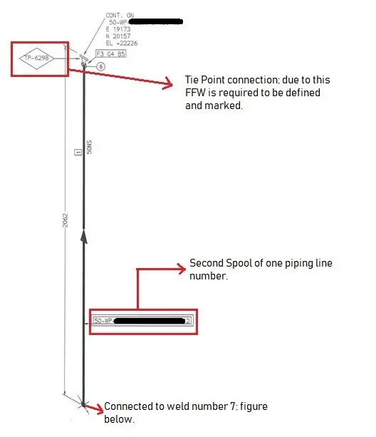
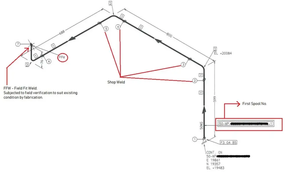
The whole assembled piping will look like the following after it is assembled at the field.
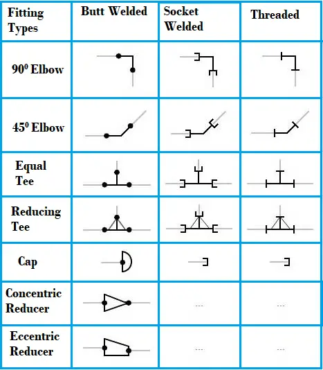
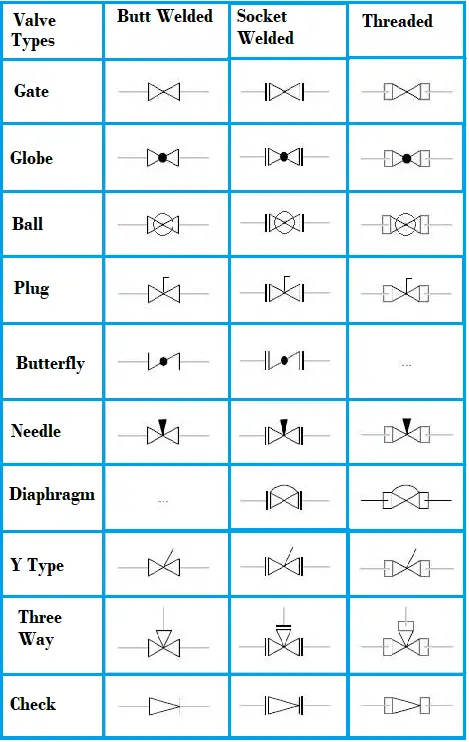
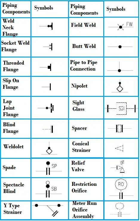
Piping Isometric Drawing Symbols
For reading and understanding a piping isometric drawing, one should learn the piping isometric drawing symbols thoroughly. Usually, all these piping and pipeline drawing symbols are similar and do not vary much from one organization to another. Knowing the isometric drawing symbols for piping and pipeline will provide various information like:
- Type of Piping Joint: Piping and pipeline drawing symbols throw lights on the type of joint like Buttweld, socket weld, or Threaded.
- Type of Piping Components: Piping symbols for Isometric drawings serve as a ready reference for the type of fittings and components.
- Instrument items: Knowing the piping isometric symbols will help in recognizing the instrument and special piping items in the isometric.
- Equipment Connection: Equipment connected to a piping system is also understood with piping symbols.
- Knowing piping symbols for isometric drawing is useful in preparing MTO/BOM.
Examples of commonly used piping isometric drawing symbols are shown below for reference purposes
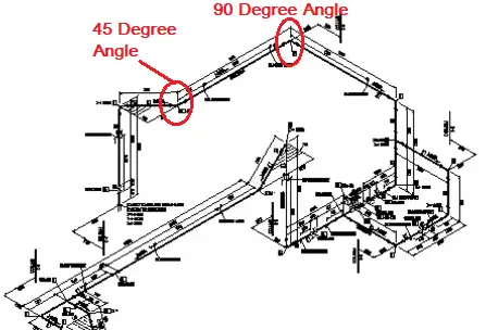
Piping Isometric Drawing 45 Degree Angle Example
A typical example of piping isometric drawing that includes a 45 degree direction change is shown below:
Piping Isometric Drawing Software
Piping isometric drawing software is an essential tool for piping engineers and designers to create detailed isometric drawings of piping systems. These tools generate the 3D representation of the piping layout, including pipe dimensions, fittings, valves, and other components. There are many piping isometric drawing software programs available in the market which makes the task of a piping designer very easy. The piping isometric drawing software packages are two types; 2D software and 3D software. In 2D software, the piping isometric is generated manually whereas 3D piping isometric software programs have the capability of automatic isometric generation.
Top Piping Isometric Drawing Software Tools
Choosing the right piping isometric drawing software tool may be difficult as there are various options available. However, most design consultancies choose the complete software program considering the complexity of the job, costs, and client requirements. Here are some popular piping isometric drawing software tools:
AutoCAD
AutoCAD is the most widely used 2-D tool for Piping Isometric Drawings. To edit or modify any part of the isometric, piping designers frequently make use of this software.
AutoDesk Plant 3D:
AutoDesk Plant 3D is an industry-standard software for piping design and isometric drawing. It offers specialized tools for creating and editing piping layouts, generating isometric drawings, and managing pipe specifications.
CADWorx:
CADWorx, developed by Hexagon PPM, is a 3D plant design and modeling software that integrates with AutoCAD to provide piping engineers with tools for generating isometric drawings, equipment modeling, and structural design.
AVEVA E3D (Everything3D):
AVEVA E3D is a next-generation 3D design and modeling software that supports detailed piping design and the creation of isometric drawings. It offers advanced capabilities for multidisciplinary plant design.
AVEVA PDMS (Plant Design Management System):
AVEVA PDMS is a powerful 3D modeling and design software widely used in the process industry. It allows for the creation of isometric drawings, as well as detailed 3D modeling of piping and equipment.
SmartPlant 3D (SP3D):
SmartPlant 3D (SP3D) is another powerful 3D plant design and modeling software offered by Intergraph (Hexagon PPM). It supports the creation of detailed piping layouts and isometric drawings, often used for large-scale projects.
SmartPlant Isometrics:
Part of the SmartPlant suite by Intergraph (now Hexagon PPM), SmartPlant Isometrics is designed to create isometric drawings and provide automated tools for generating accurate and standardized piping isometrics.
SolidWorks Piping:
SolidWorks, a popular 3D CAD software, includes a Piping add-on module, that allows users to create detailed piping designs and generate isometric drawings directly within the SolidWorks environment.
Pipe-Flo Professional:
Pipe-Flo Professional is a piping system design and analysis software that includes features for generating isometric drawings, as well as assessing the hydraulic performance of piping systems.
AutoCAD MEP:
AutoCAD MEP is a specialized version of AutoCAD designed for mechanical, electrical, and plumbing (MEP) systems. It includes tools for creating isometric drawings of piping systems.
MicroStation:
MicroStation is a CAD software platform developed by Bentley Systems. It can be used for piping design and the creation of isometric drawings, especially when integrated with Bentley’s other plant design software solutions.
PDS (Plant Design System) by Intergraph (Hexagon PPM):
PDS is a comprehensive plant design and modeling software suite that includes tools for creating isometric drawings, 3D modeling, and engineering analysis for piping and equipment. This software is seldom used in recent times.
Bentley AutoPIPE:
Bentley AutoPIPE is a comprehensive software solution for piping analysis and design. It includes features for creating isometric drawings, analyzing stress and load conditions, and ensuring compliance with industry standards.
CAESAR II:
While CAESAR II is primarily a pipe stress analysis software, it can generate isometric drawings as part of its output. It is commonly used to verify the structural integrity of piping systems.
Online Video Courses on Piping Isometrics
If you wish to explore more about piping isometrics, you can opt for the following online video course
- Piping Design Engineering and Piping Isometrics Masterclass
- Piping Isometrics Demystified
- Piping Fabrication with Isometrics
Video Tutorial of Basics of Piping Isometric Drawing
The following video tutorial on the basics of piping isometric drawing will clarify some of your doubts.
Some more Resources for you…
Salient Points to check while reviewing Piping Isometric Drawings
Preparation of Piping Isometrics
Types of Piping Drawings
References
- Credit to other sources: svlele.com, wermac.org, pipingengineer.org, thepiping.com, spedweb.com, enggcyclopedia.com, rishabheng.com
Hi,
I would like to familiar with isometric Piping. My basic is Diploma in Mechanical Engineering and my experience is MEPmechanical side. Like PHE and Fire Fighting only 2D with arch Background. Max Pipe size i handled 12″in Fire fighting. I would like to learn more in Piping Isometrics
Hi Ramesh,
Thank you for your comment. As a start, you may take any P&ID and compare it to the respective Isometric drawings. Start from one point till the end. I believe, over time you will master it.
Hi,
I have a Electrical Designer background and the job I have now would like me to do Piping ISO’s.
I do not know where to start at I have been looking at the pipe they want to install on the Area and I’m having all kinds of trouble. So if you can help I would appreciate it. Where do I need to start at?
Excellent info about piping
I would like too share knowledge about piping scope. I have done Bachelor’s degree of Mechanical engineering also completed Piping design (PDMS) software as per ASME.
Good knowledge of piping, isometric, P&id, layout, BOQ & BOm.
Good knowledge of Code & Std.
Good knowledge of Pipe/Wall thickness calculation.
I have 3 years experience in oil & gas field
For more query/ information please feel free to contact me.
Thank you
Good morning bro
how do I contact u..please if u can add me on what’s app I shall b grateful.08066081642
Good Evening Mohammad,
My name is Michael, I’m an apprentice steamfitter, and I want to become a journeyman detailer. I am trying to wrap my mind around two drawings and would greatly appreciate your help if you could email me at mikeparcio2328@gmail.com I would really appreciate any help and guidance you could provide. Thank you and have a great day/night.
Thank you!
Please can i reach out to you on WhatsApp?
Very nice .Knowledge stetus.
do you have examples of house plans in PDF
Dear All,
Hi, i’m kris with mechanical engineer background. And i’m as employee at one of foreign company in Indonesia. I would to asking you about piping symbols for uPVC or HDPE material. Is that equal with socket welded symbol for steel pipe material ?
Thank you.
piep line kase napa jata hai uska formula bataeye
Any samples of combined/mixed piping matl iso, i.e., s/s & pvc piping? Tnx.
Hi,
I am a piping engineer, with more than 6 years of site experience.
I want to shift from site to design, which was my primary interest.
Can you guys please suggest / advice, what should I do to get it into design?
Excellent tutorial. Thanks
Thank you for this very useful article Ma’am.
Its very useful info.
Hi, can you plz share the formula-how to calculate the total weight using Pipe dia, schedule and length of the pipe..
for example: pipe dia 12″, SCH 40s, lengh 4m
E3D is the aveva software for used to model piping. It is used in oil and gas industries. We can extract isometrics.
Dear sir
Sabse hard isometic droing ka tampalet banane ka koe Aasan tarika bataye
Thanks for sharing.
K