
Drawings in Piping are essential documents in the design, construction, and maintenance of piping systems in various industries, including oil and gas, chemical processing, power generation, and water treatment. These drawings provide a detailed representation of the piping layout, components, and specifications, ensuring that the system functions efficiently and safely. This article explores the different types of piping drawings, their purposes, and how they are used throughout the lifecycle of a piping system.
What is a Piping Drawing?
The main purpose of a piping drawing is to communicate fabrication and construction requirements clearly in a simple and easy way. Piping drawings are schematic representations that define functional relationships in a piping or pipeline system. All these piping diagrams are prepared in such a manner that even non-technical professionals can easily understand. Piping drawings provide guidelines for the design and construction activities of piping items. Their main aim is to communicate design intent, construction details, and operational requirements.
Types of Piping Drawings
For designing process piping or power piping, mostly five types of piping drawings are developed. These drawings are generated from the schematics, basic design basis, and specifications for process/power piping.
The most common types of piping drawings in engineering organizations are:
- Piping Plan Drawings
- Process Flow Diagram
- Piping and Instrumentation Diagram
- Plot Plan Layout Drawing, and
- Piping Isometric Drawing
Piping Plan Drawings/General Arrangement Drawings (GAD)
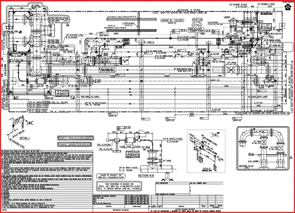
The piping plan or general arrangement drawings (Fig. 1) show all major equipment, its north/south and east/west orientation, and all piping leading to and from equipment are developed by piping designers. All Main piping items (valves, fittings, etc), instrumentation, access ladders, and platforms are shown.
The General Arrangement Drawing usually shows a plan (top) view with elevations (side) and sectional drawings with piping dimensions and details including line numbers, size, specification, the direction of flow, etc. to help the piping designers extract all necessary information for isometric or fabrication drawing preparation. GA drawings are used to convey the spatial arrangement of components and their relationships within the system.
General arrangement drawings are produced for specific mechanical equipment as well which presents major dimensions in two-dimensional views. All nozzles, supporting details, etc. are indicated.
A piping plan drawing provides the following necessary information:
- Arrangement of pipes, equipment, and instruments in relation to the structure of the plant or facility.
- Pipe routing, length, and coordinates.
- Spacing or centreline distance between one pipe to the other line.
- Correct positioning of the piping assembly on the pipe rack.
- Type of pipe supports required in the piping and pipeline systems and the support spacing.
- Instrument connection to the piping.
- Highlights areas that need to be accessible for maintenance and operation.
- Equipment connection, etc
Piping General Arrangement (GA) drawings are very important for Layout Visualization, Construction Planning, and coordination between different disciplines, such as structural, mechanical, and electrical engineering.
Process Flow Diagrams (PFD)
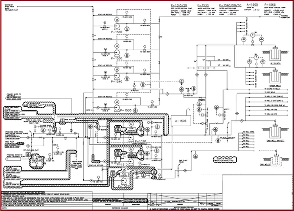
A PFD or Process Flow Diagram (Fig. 2) is an unscaled drawing or schematic that describes the process of transferring fluid inside the piping. It will:
- state the fluid material that is conveyed by the piping.
- specify the rates of flow.
- list the equipment required for the plant
- and provide basic line list parameters like pressure or temperature.
- equipment capacity and basic operating information.
- all critical valves including control valves.
A process flow diagram explains relationships between major equipment of a plant and informs the fluid flow direction and connectivity between various equipment through the piping system. PFD is important to easily understand any process, provide quality control, and increase efficiency.
The pipe sizes, pipe class, instrument tags, safety valves, isometric number, type of valves, etc. are not determined yet. The data from PFD are then transferred to P&ID or PEFS.
Piping & Instrumentation Diagram (P&ID)
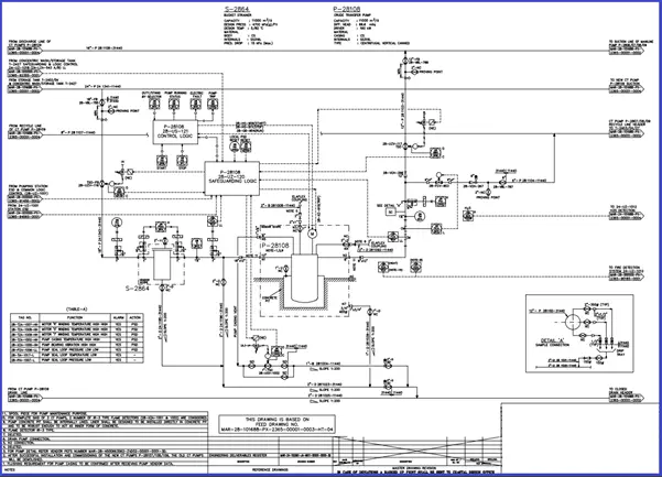
Also known as Process Engineering Flow Scheme or PEFS. The P&ID (Fig. 3) is similar to PFD but more detailed. It is a single-line schematic drawing that includes all equipment, instruments and controls, major valves, and line sizes with pipe specifications. It is the first important document that controls the activity of all other related engineering groups. P&IDs serve as a master document and It contains all the data necessary for various other design groups to proceed to the next steps of design and produce their deliverables. Click here to learn the major differences between PFD and P&ID.
Plot Plan Layout
A plot plan (Fig. 4) or site plan is produced by the piping designer which shows a schematic of the whole site with boundaries, roads, buildings, plant areas, equipment layouts, utility runs, and other constructions of the existing project, etc. at a properly defined scale. So it gives an overview of the entire plant. This allows the piping engineer to arrange equipment to optimize the design to reduce cost.
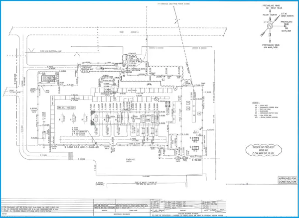
Plot plant as a type of piping drawing is drawn in a to-the-scale drawing. The main purpose behind a plot plan layout drawing is to find the exact area available and how those spaces are used for piping, structure, and equipment positioning. A Plot plan provides the following information:
- Total area details of the process plant
- The exact location of equipment, buildings, roads, etc.
- The total number of equipment to be erected in the plot.
- Length of a pipe rack.
- Area of each individual unit.
- Battery limit details.
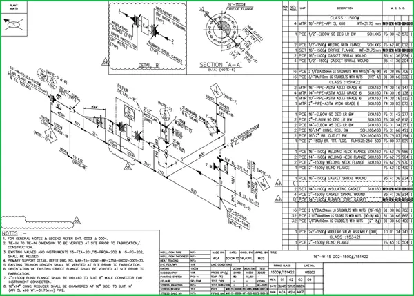
Piping Isometric Drawing
Piping Isometric drawings (Fig. 5) represent the pipe routing with proper dimensions including all piping items and equipment. They are not to scale, single-line diagrams with symbols for pipe components, weld points, and supports. Isometric drawings are used:
- By fabricator to fabricate the line.
- By piping material group for purchasing materials
- By the Construction, the team to erect the piping items on the site following proper routing.
All the above drawings are very important project documents and must be prepared with the utmost thought and care to reduce the amount of rework at a later stage. Click here to learn more details about Piping Isometric Drawings.
I am basically mechanical engr and I worked many years in MEP field. Now I would like to learn piping isometric spools from the GA Piping Plans. I need to start from where? How to fix project north in a open site etc.
I like the information on here. It very informative and detailed. I’m studying CAD, and currently doing a class in process piping. However, I am still indecisive about what area in design to specialize, in terms of design. But truthfully, your blog is informative, and thanks.
Dear Anup
Hops Doing well
pls Share Details Classification/Explanation of Pipe’s on The Basic of NB, DN, OD, Seamless, and many more Terminology..
Thanks
Wait for Your Response.
Regard
~Deepak Verma
Good article