
Piping support plays a very crucial role in the proper functioning of piping systems. Pipe support carries the pipe weight with contents. To maintain the integrity of the piping system, A pipe must be supported following a proper pipe support span. Pipe support engineering is very critical for the success of any project as an accurate and judicious selection of piping support is required. Pipes as irregular space frames are not self-supporting so must be supported. Piping Loads are transmitted from pipe to supporting structures with the help of pipe supports. Proper pipe support knowledge during the layout stage is advantageous.
The piping system is a major part of any hydrocarbon industry. Proper pipe support knowledge during the layout stage is advantageous. Piping Loads generated due to Weight, Pressure, Temperature, or Occasional Events have to be transmitted from pipe to supporting structures with the help of appropriate pipe supports.
Difference Between Pipe Support and Pipe Restraint
The term “Restraints” is invariably used for pipe supports. However, there is little difference between pipe support and restraint. Pipe supports are used to support the piping system by carrying the vertical load whereas pipe restraints limit the movements of the pipe so take care of the horizontal loads. So from the definition, Simple Rest is pipe support but Guide and line stops are pipe restraints. Normally, All pipe restraints come in combination with piping supports. Pipe support and restraints, combined can be said pipe support systems. Henceforth, the term pipe support refers to the pipe support system.
Purpose or Functions of Piping Support
The various functions that pipe support serves are as follows:
- To prevent Pipe stresses above allowable.
- To eliminate the Leakages in joints.
- To absorb Excessive Line Vibrations.
- To counter the undesirable effects of Seismic, wind, water hammer, slug, and other dynamic loadings.
- To remove unintentional disengagement (lift-off) of piping from its supports.
- To prevent excessive pipe sag (Normally more than 10 mm for process piping, 2.5 mm for power piping; and 12.5 mm for GRE/GRP piping)
- To eliminate exposure of elements to temperature extremes, outside their design limit.
- To limit undesirable line movements to protect sensitive equipment (pumps, compressors, turbines, fired heaters, etc) against overloading.
- To redirect pipe thermal movements in the favorable direction.
- To reduce excessive loading in support itself.
For the proper working of the piping system, it has to be supported properly. The major purpose of pipe supports can be elaborated as follows:
Piping Supports for Carrying Weights
Pipe Supports are required to support the line during all conditions i.e. during operation as well as during testing. In the case of the vapor line, this difference will be very large due to hydro testing. Supports should be designed for this load (unless otherwise decided in the project). Sometimes the line is capable of having a longer span but the load coming on the support may be very large (especially with large-diameter pipelines). Then to distribute the load uniformly, the number of supports should be provided with a smaller span.
Notes:
- It may be noted that during testing conditions there is no thermal load.
- All spring supports are locked during testing.
Piping Supports to Take the ‘Thermal or Expansion Load’
Whenever thermal expansion is restricted by pipe supports, it introduces additional load on the support. Support restraints must be designed to take this load in addition to all other loads.
Pipe Supports transfer the Occasional Earth Quake Loads
The earthquake is normally associated with horizontal acceleration of the order of 1 to 3 m/sec2. This is around 10% to 30% of the gravitational acceleration and introduces a horizontal force of about 10 to 30% of the vertical load (or supported mass). While designing pipe support, this should be taken care of.
Take ‘Hydraulic Thrust in Piping’
The hydraulic thrust (Fig. 1) in the pipeline is present at certain points such as the pressure-reducing valve, relief valve, expansion bellows, etc.
If the control valve has a large pressure differential (large pressure drop) and the line size is high, then this force can be very high.
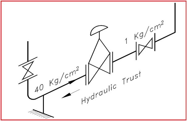
The support should be provided and designed to take this load, otherwise, this will load the piping system and may cause failure.
Piping supports absorb ‘Vibration of Piping System‘
When the pipe is subjected to moving machinery, pulsating flow, or very high-velocity flow, the pipe may start vibrating vigorously and ultimately may fail, particularly if the span is large. To avoid this it may be required to introduce additional supports at a smaller span apart from other requirements. It may not take axial load but must control lateral movements.
Carry the ‘Occasional Wind Load’:
Wind introduces lateral load on the line. This load is considerable, especially on large diameter pipes, and increases as line size is increased. This load tends to sway the line from its normal position and the line must be guided properly against it to avoid any kind of malfunction. In the case of large-diameter overhead lines, supported by tall support extended from the floor, wind load introduces large bending moments and should be considered critically.
Support the System during the ‘Transient Period of Plant & Standby’
Transient Condition: Transient condition refers to the start-up or shutdown condition in which one piece of equipment may get heated up faster and the other one gets heated slower. Due to this the expansion of one piece of equipment that in normal operation will get nullified, may not get nullified, and exert a thermal load on supports.
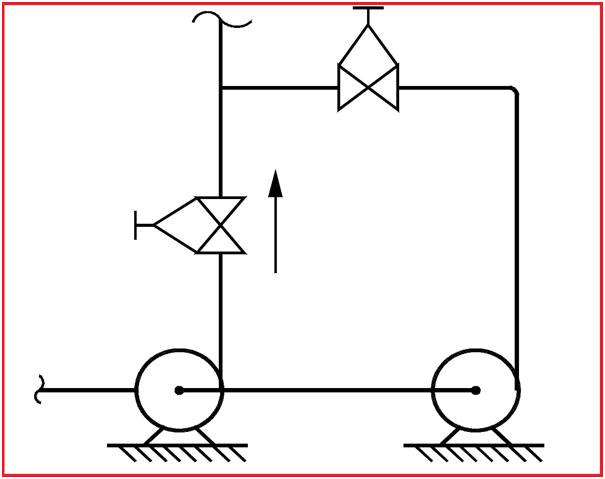
The standby condition is also similar. If there are two pumps, one being standby and both connected in parallel (as shown), the design and operating temperature of both connections will be the same. But the expansion of two parallel legs will not be nullified because at a time only one leg will be hot, and the other will be cold.
Piping Supports for ‘Noise Control’
In most plants, noise is resulting from vibration and if such vibrations are controlled, noise is reduced to a great extent. In such lines, between the clamp (i.e. support) and pipe, the asbestos cloth is put to absorb vibration and avoid noise.
Noise due to pulsating flow can be reduced by using a silencer in the line. Still, if it is not below an acceptable level acoustic enclosure may be used. Piping Insulation over the line also helps in reducing the noise.
Support the System during ‘Maintenance Conditions’
When for maintenance certain equipment or components like the valve are taken out, the remaining system should not be left out unsupported.

Referring to FIG-3, support ‘S1’ will be sufficient but when valve ‘V1’ is taken out for maintenance there will not be any support for the vertical leg. Therefore second support ‘S2’ may be required to take care of such conditions.
Piping Support for ‘Shutdown Conditions’
In shutdown conditions, all equipment may not be in the same condition as in operating conditions. For example, refer to the pump discharge line in Fig-4, Point A is resting, Point B & C are spring supports and Point D is the pump discharge nozzle. The springs are, designed based on weights considering the weight of fluid as well as pipeline and thermal movements. But during shutdown conditions, the fluid may be drained and the pipe becomes lighter. Hence, the spring will give an upward reaction and shall load the nozzle ‘D’ beyond the permissible limit.

In this case, a limit stop is used which will not allow Point C to move up above the horizontal level. (However, it will allow downward movement during operating conditions).
Use of Pipe Support for Erection Conditions
Erection conditions can be different than the operating conditions which should be considered while designing supports.
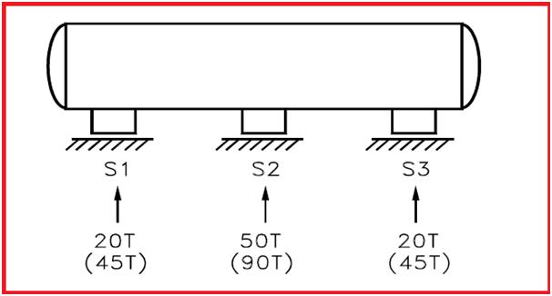
For example, for normal operation, a long vessel supported by three supports, S1, S2 & S3 is shown in FIG-5. If support S2 is higher then all load will act at S2 only. During an erection, if the level of S2 is lower then the entire load will be divided into two supports S1, and S3 only. Therefore the foundation of S1, S2 & S3 should be capable of taking such conditions.
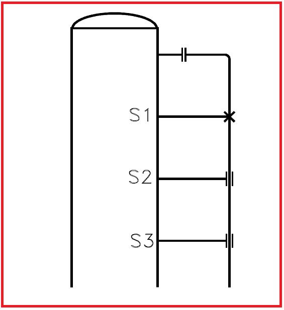
A pipeline supported by S1, S2 & S3 taken from the vessel is shown in above FIG – 6. During operation, there will be no weight at S2 & S3 (as it is the only guide), but wind conditions will be there. Loads due to such conditions must be considered while designing the supports.
Codes and Standards for Piping Support Design
The following codes and standards are used for piping support design.
- ASME B31.3: Process Piping Code ASME B31.3 is the base code for pipe-supporting requirements.
- MSS-SP-58– Establishes the material, design, and inspection criteria to be used in the manufacturing of standard pipe supports. (USA)
- MSS-SP-69- Provides recommendations for the selection and application of pipe supports. (USA)
- MSS-SP-89- Provides recommendations for the fabrication and installation of pipe supports. (USA)
- MSS SP-89: Provides fabrication and installation practices for Pipe Hangers and Supports.
- MSS SP-90: Explains guidelines on the terminologies for Pipe Hangers and Supports.
- MSS SP-77: Provides guidelines for Pipe Support Contractual Relationships.
- BS-3974- Specification of pipe supports 1, 2, 3. (UK)
- VGB-R-510 L- Standard supports guidelines. (Germany)
- RCC-M- Specifications for pipe supports. (France)
- MITI 501- Technical regulations (Japan)
Piping Support Design and Selection
The complex requirements of today’s piping support design are reliable functioning, maintenance-free operation, economical and easy installations, quick delivery of components, and low unit prices.
Major Criteria (Parameters) governing the pipe support hardware selection are
- Pipe Support function,
- Pipe Material for construction
- The magnitude of expected operational and occasional load,
- Available space limitations,
- Design temperature of the piping system,
- Expansion effects of the piping systems,
- The piping attachment and supporting structure material compatibility,
- Piping insulation/cladding, material, and thickness
- Suitability to the environment,
- Ease of operation, inspection, and installation.
Piping Support Types
Pipe Supports are categorized based on the following parameters
- Based on the attachment with Pipe
- Primary Piping Support
- Secondary Piping Support
- Based on Support hardware rigidity
- Rigid support
- Resilient Support/ Elastic Support
- Adjustable Support
- Based on Piping Insulation
- Piping Supports for Hot Insulation
- Piping Supports of Cold Insulation
- Piping Supports for Acoustic Insulation
- Based on Welding
- Welded Pipe Support
- Clamped Pipe Support
- Based on the Pipe Support function
- Resting Support
- Guide Support
- Axial Stop or Line Stop
- Anchor Support
- Based on Pipe Orientation
- Piping Support for Horizontal Pipe
- Pipe Support for Vertical Pipe
1. Types of Piping Supports based on the attachment with Pipes
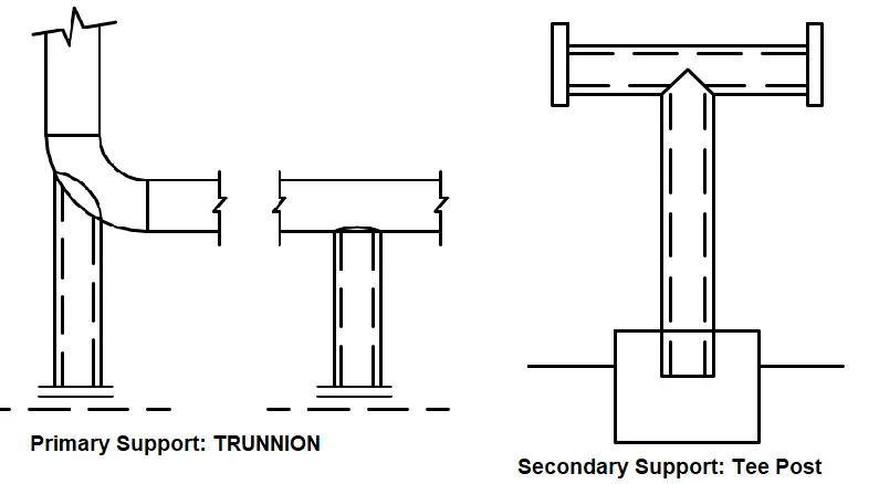
Primary Piping Support
Pipe Supports that are directly attached to the pipe are called Primary pipe Supports. For example, Shoe support, Clamp Support, Guide Support, Line Stop Support, Trunnion Support, etc. The design and selection of primary pipe support (Fig. 1) is the responsibility of the piping team.
Secondary Piping Support
Pipe supports that are not directly attached to the pipe are called secondary piping supports. Support Brackets, Secondary Steel members on which pipe or primary supports rest, Tee Posts, Goal Posts, sleepers, racks, etc. are examples of secondary pipe supports. The design and selection of secondary pipe supports (Fig. 7) are the responsibility of the civil team.
2. Types of Pipe Supports based on Hardware Rigidity
Rigid Supports
Rigid supports provide rigidity at least in any one direction to restrict the pipe displacement in those direction(s) without any flexibility in that direction. Rigid pipe supports can serve as a Rest, Guide, Line Stop, or any combination of these. A fixed anchor is also a rigid support that provides rigidity in all six degrees of freedom. Typical examples of rigid supports are pipe shoe support, Rigid Strut Support, Trunnion Support, Saddle Support, etc.
Resilient Supports
Resilient or elastic supports use an elastic member for carrying pipe load and allow the pipe movement in the desired direction. Spring Hanger Supports which use a compression spring are known as Resilient Supports.
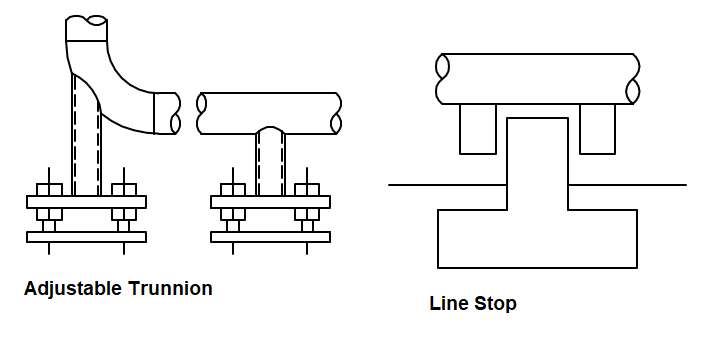
Adjustable Support
An adjustable support (Fig. 9) can be adjusted at the site during plant operation. These supports are normally provided for pipe and equipment alignment purposes. The first support from a pump suction and discharge pipe is provided with an adjustable pipe support. Sometimes the first support from a storage tank pipe system is also provided as adjustable support to adjust the support length in case of tank settlement.
3. Pipe Support Types Based on Piping Insulation
For hot insulated pipes, piping shoe/saddle supports are used for support. For cold insulated pipes, cold shoes (cradles) are used while supporting the pipes. For piping systems having acoustic insulation, special arrangements are made to isolate the vibrating pipe and supporting structure.
4. Types of Pipe Supports based on Weldng Requirements
Based on welding requirements, the supports may be welded or clamped. Welded pipe supports (shoe supports) are used on piping systems where welding is permitted. However, for certain piping systems, where welding is difficult or not allowed, clamped types of piping shoe supports are used.
5. Piping Supports based on the Function of the Support
Depending on the pipe support function, piping supports may be known as Rest, Guide, Hold Down, Anchor, Axial Stop, etc. These mentioned terms are defined in the pipe support terminology section.
6. Piping Supports Based on Pipe Orientation
Again, pipe supports can be differentiated based on the orientation of the pipe run. The support types and functions may be different when using the same support in a piping system of vertical or horizontal orientation. For example, a hold-down and guide support in a horizontal pipe will act as a hold-down and guide but the same in a vertical pipe may act as an all-around guide.
Piping Support Rules/Guide for Optimization
The following points need to be followed for optimized pipe support.
- Group pipelines so as to minimize the number of structures needed solely to pipe supports.
- Route lines close to the possible point of supports ( i.e. grade or structure which is provided for other purposes.)
- Supports or braces are to be located at or near neutral points. (thermal null points)
- Supports to be located as near as possible to concentrated loads such as valves, flanges, heavy actuators, etc.
- Piping susceptible to vibration such as compressor connected lines to be supported independently. The use of hold-down or similar supports offers resistance to motion and provides some damping capacity to be used rather than hanging-type supports.
- Piping connected to the top of the vessel to be advantageously supported from the vessel to minimize relative movement between supports and piping.
- Always maintain the distance between supports as per the project specification recommended support span table. ( it is applicable to straight-run pipe length only.) When a change of direction in a horizontal plane occurs, it is suggested that the spacing be limited to ¾ times the standard pipe span.
- Sufficient space to be provided to facilitate support assembly installation, inspection, and maintenance.
Piping Support Terminologies and Definitions
Brace or Bracing Support- A device primarily intended to resist displacement of piping due to forces other than thermal expansion and gravity.
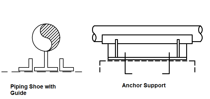
Anchor Support or Fixed Support- A rigid restraint providing substantially full fixation is termed an anchor. Anchor support restricts all six degrees of freedom (three translational and three rotational) and does not allow the pipe to move in any direction. Normally Full-Welded or Bolted supports are called anchor supports. Full Anchor supports (Fig. 10) are rarely used in piping systems.
Stop- A device that permits rotation but prevents translatory movements of piping. A line stop or axial stop (Fig. 9) prevents pipe movement in the axial direction of the pipe. It is also known as a stopper.
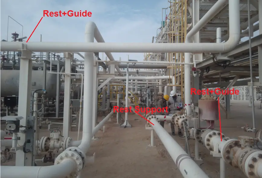
Guide- A device that prevents the rotation of one or more axes is called a guide (Fig. 10). Guide supports (Fig. 8) prevent Lateral pipe movements.
Hold Down Support- A device that holds the pipe in position disallowing vertical upward movement or allowing decided upward movement. Hold-down supports prevent pipe disengagement from the Support structure.
Hanger- A support by which piping is suspended from a structure that functions by carrying the piping load in tension.
Rest Support or Sliding support- A device that is provided below piping to take gravity loads, offering no resistance other than frictional to horizontal motion. Rest supports (Fig. 8) do not allow the pipe to sag or move downward.
Damping element- A device that increases the damping of a system offering high resistance against rapid displacement, caused by dynamic loading while permitting essentially free movement.
Dummy Leg – Basically an extension pipe welded to an elbow, to provide support either as a resting, anchor, etc.
Popular Types of Piping Supports
The following types of piping supports are most popular in the oil and gas, and petrochemical industry.
- Hanger Supports – 1) Variable Hanger 2) Constant Hanger 3) Rigid Hanger. Click here to learn more about Spring hangers.
- Dynamically Loaded Supports – 1) Struts 2) Snubbers 3) Sway Brace 4) Energy absorbers 5) Pipe Clamps 6) Pipe whip / Hold down restraints.
- Pipe Bearing Components – 1) Pipe Saddle 2) Pipe Shoe 3) Pipe Trunnion 4) Wear Pad.
- Threaded Members – 1) Welding nut 2) Welded beam attachment 3) Clevis 4) Turnbuckle 5) Tie rod 6) Stud bolt, nut, locknut, spring washers, etc.
- Slide Bearing Plates – Teflon, Stainless steel, graphite.
Pipe Support Manufacturers
The number of Piping Support manufacturers is quite long. However, the following are the most popular:
- Piping Technology and Products Ltd.
- Carpenter and Paterson Ltd.
- Lisega Ltd.
- Binder Group Ltd.
- Pipe Support Group Ltd.
- Sarathi Engg Ent Pvt Ltd.
- Anvil Group etc to name a few
Piping Support Engineering
Minimum Data required to start pipe support engineering are
- Piping GAD
- Electrical and Inst cable trench/tray layouts
- Civil and Structural drawings
- Piping specification and line list
- Insulation specification
- Valve’s weights
- Equipment connection displacements
- Stress recommendations (Stress isometrics) and Support loads.
Pipe Support Span
Typically piping is supported at regular intervals on steel supports embedded in concrete foundation or directly on the steel structure. The distance between supports is the supporting span.
The basis for the calculation of the maximum support span
There are three main factors that affect the support span.
- Stress
- Deflection/ sagging and
- Frequency of piping system (for two-phase flow lines, reciprocating equipment connected lines, vibrating lines, etc.). Click here to learn more about pipe support span
Piping Support Rules
Supporting Stress Critical Lines
Supporting Criteria for Critical Lines: The support location is usually decided by piping designers. The type of support is decided by stress engineers. Primary attachments and secondary supports are selected by the designers whereas Line stop/Guide supports and gaps are informed by stress engineers.
Supporting non-critical lines
- Senior designer to decide on support type and location based on
- Support span
- Guide span
- Concentrated loads e.g. valves, instruments, etc
- For the Long piping legs, the stress engineer is to be consulted
Supporting Insulated Pipes
- No direct resting, pipe shoe to be provided
- Minimum clearance between the insulation and the supporting structure shall be at least 50 mm.
Supporting of Non- Insulated Pipes
Directly rested except following
- Pipes with sizes larger than DN 600
- CS pipes with less than SCH 20
- SS pipes with less than SCH 10S
- The pipe that requires a slope
- Dissimilar material to avoid galvanic corrosion
- The pipe is to be supported on a pipe shoe to avoid damage to the pipe wall
Vertical piping support
For vertical piping support, the below-mentioned guidelines are followed
- Standard piping support span chart does not apply
- Supports to be located on the upper half of the portion (i.e. above C.G. of pipe)
- The vertical guide spacing is normally lower than the horizontal guide spacing
- Clamped supports with weld-on shear lugs to avoid the pipe slipping under the clamp
Special Pipe Supports or SPS
The pipe supports that do not fall in the above category are called special pipe supports. Various kinds of special pipes are required for critical lines. The design is normally slightly complicated and a separate drawing is prepared for each special pipe support. For example
- Spring hanger along with Guide
- Hanger along with guide and line stop
- Normal primary support requiring additional strengthening due to increased load, etc
The drawing is normally prepared by the pipe stress or pipe support engineer and checked by a civil engineer to ascertain the structural member load-carrying capability.
Differences Between Piping Support and Pipeline Supports
The main function of supports in both piping and pipeline systems is usually the same. However, there are certain distinct differences between the piping support and pipeline supports that are specified in the table below:
| Feature/Aspect | Piping Supports | Pipeline Supports |
|---|---|---|
| Scale and Length | Used within facilities, handling shorter lengths. | Used for long-distance pipelines (hundreds or thousands of miles). |
| Environment | Controlled environments like plants and refineries. | Varied and often harsh environmental conditions (deserts, mountains, etc.) |
| Design Considerations | Managing weight, thermal expansion, and vibrations of pipes within a facility | Addressing large-scale thermal expansion, ground movement, and environmental factors over long distances. |
| Common Support Types | Hangers, saddles, guides, anchors, spring hangers, rigid hangers, and various complex arrangements. | Pipeline supports are usually simpler as compared to piping supports. Typical examples are sleeper supports, anchor blocks, above-ground piers, etc |
| Operational Context | Industrial facilities, refineries, power plants, processing complexes, etc | Long-distance pipelines, transporting fluids or gases across vast distances. |
| Support Span/Spacing | Usually less due to high temperature. | The support span in pipelines is comparatively large due to low-temperature applications. |
This table provides a clear comparison between piping supports and pipeline supports, highlighting
Online Video Courses on Piping Support
To learn more about piping support design and engineering you can opt for the following video course.
Few more Resources for You…
An article on Piping Support span
Supporting of Dual Insulated Piping System
Dynamic Restraints
Piping Stress Analysis
It’s a great article with proper explanation.Thanks a ton for this wonderful information. Sir, I have a request if you can provide an article on example of dummy piperack analysis in CAESAR-II with selection of shoe type supports and where to place those supports in addition where to place expansion loops, it will be so grateful of you.
Wow, I had no idea that there was so much to know about industrial piping systems. Although, it does make sense that you would need to find a way to support them. After all, by using things like hangars and pipe bearing components you can keep the pipes from crashing down on your heads.
Something to always check when installing pipe supports: (a) Check that the additional lines installed on the beams have not deflected the beams so that the other lines are still adequately supported.(b) Ensure that the lines during commissioning have not locked up the other lines and preventing them to move.(c) Ensure that the line have clearance necessary to absorb any movement.
There are so many considerations to take into account when commissioning a plant piping.
If in doubt call an experienced piping engineer out to check and verify your observations.
Very useful Information,
I have met with a problem where we have provided 800 DN CHW pipe without saddle plate in our support design ,
Can anyone please provide any reference to the codes or standards which support or reject this design,
does any code says anything about necessity of saddle?
Hi 1. Here that location required pipe shoes not only saddle?
2. Is it that location is simple rest or semi anchoring?
See if it is simple rest… provide a clamped shoe or welded shoe.
If u r not providing a shoe. Then u have to check pipe intendation check on that location to proceed.
Because line contact is not allowed such big bore. Wall thickness also played important role.
Thank you for reply, that location was simple rest,, so clamped shoe will be more suitable I think,,,
How to perform intendation check?
Boss it’s very valuable notes . Thank you so much sir.
I am Rajprabhu Mari working as a QA/QC Piping inspector in oil and gas. The notes that you shared is very helpful for me.
very Nice blog sir , thank you
Very informative website…things are explained in a very simple terms..thanks a lot for sharing this knowledge..
Hello How are you?
Mi name is Jose Bermudez,
Do you have piping support standard to PSV in the top of the towers?
How the axial line stops in horizontal pipe is to be planned when its placed over pipe sleeper way where sleeper concrete width is too much say 500mm?
Hi Anoop,
All is well.
Please advise me how to calculate pipe loads on support locations? Pipe span is calculated and we confirmed the support locations. Now the supports need to be designed based on the point loads. Please advise.
Hi… I want to simple calculator which gives the load on piping support …
Ex.. one pipe with 3 support s .. end fixed and center guided …. What will be the load on these supports and chage if it’s inclination is changing to 0 degree, 20 degree, 30 deg, 45 degree, 60 degree
Excellent Article
I have been a Pipe Supporter for over 30 years and many times engineers and managers have mocked Pipe Supports as, easy and one time “all you do is put a shoe on a pipe”. I do hope people like that read your article but in truth they will probably not, with the excuse “its not worth reading as there is nothing to it”; how wrong they are. Have fun.
This wonderful information about piping supports in brief which helps to understand quickly.
Please mr, how can I calculate the velocity erosion and maximum velocity of the pipe, please gave me that equation ,thanks
This information is gold, thank you very much.
how to use welded shoe on pipes (insulated) in severe weather conditions. Like -40 DegC. Cryogenic supporting are very expensive. Also wondering the materials to be used. Better using the clamping supports around the insulation. Making an exeption on the anchor points in the pipeline design.
HOW TO FIND OUT LOOP NUMBER FROM P&ID
Hi,
Thank you for your valuable information. it is very helpful.
if S is lower load will be shared by S1 & S3 Only , but you are given as S1 and S2 in Horizontal Vessel may be typo error. Please confirm.
Thanks & Regards,