
Pipe support spans play a crucial role in maintaining the longevity, efficiency, and safety of aboveground piping and pipeline systems. Pipe support span is also known as pipe support spacing. A proper pipe support span not only reduces the pipe supporting problems but also adequately supports pipes at regular intervals to reduce failures associated with improper supporting. In this comprehensive guide, we will discuss the intricacies of pipe support spans, covering design considerations, factors on which it depends, best practices, and pipe support spacing charts based on different codes and standards.
A. What is a Pipe Support Span?
Pipe Support Span is defined as the optimum distance between two consecutive pipe supports to avoid excessive stress, sagging, bending, vibration, or failure of the piping or pipeline system in extreme cases. It ensures that the piping system remains securely in place throughout operation. Adequate pipe support spacing is synonymous with
- Structural Integrity
- Reduced Maintenance
- Safety
- Operational Efficiency
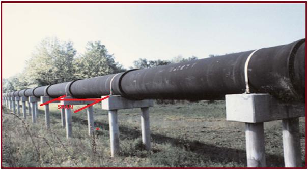
We all know that while routing aboveground piping or pipeline from one part or equipment to another we have to support the pipe at some definite spans. A properly designed pipe support span helps the piping design personnel to support pipes at regular spacings, thus reducing his work for unnecessary calculations. Pipe Support Span is also known as Pipe Support Spacing. Refer to Fig. 1 which defines the pipe support span for a pipeline system.
B. Factors on Which Pipe Support Span Depends
Various factors influence the pipe support span. In the following section, we will discuss 11 such important criteria that dictate the Pipe support spacing.
1. Pipe Material:
Pipe Support spacing varies with pipe material, For non-metallic pipes, the support span is lower than metallic pipes of the same size. Even Stainless Steel pipes have lower pipe support spacing as compared to Carbon steel pipes.
2. Nominal Diameter of Pipe & Schedule:
With the increase in pipe diameter and schedule, the pipe support span increases. That is the reason you will find that a 10-inch pipe has more support span as compared to a 4-inch pipe support spacing.
3. Type of Fluid Service:
Piping support span varies with fluid service; Pipes carrying liquid service have less support span as compared to pipes carrying gaseous fluids. This means with an increase in the density of the flow medium pipe support spacing decreases.
4. Type and Thickness of Insulation Material:
With an increase in thickness and density of the pipe insulation material, pipe support spacing reduces. An increase in insulation density and thickness imposes more load on the parent pipe which needs to be supported by increasing the number of supports which means the pipe support span reduces.
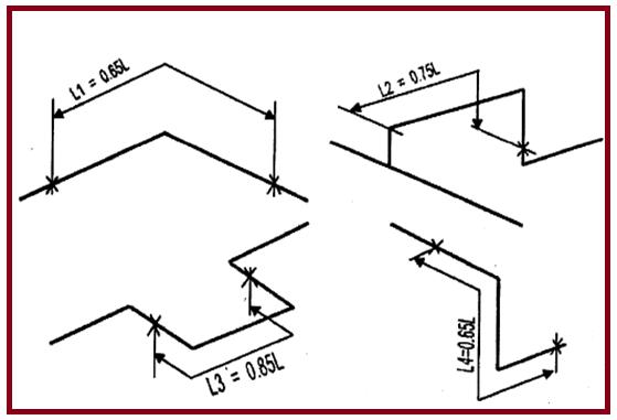
5. Piping Configuration (Straight pipe and Pipe with elbows):
Pipe support spacing is dependent on the piping routing or geometry. A straight pipe has more support span as compared to pipes with directional changes. Because of this reason, to find out the span for piping including elbows, the straight pipe span is multiplied by a factor as shown in Fig. 2.
6. Locations of Valves and Rigid Bodies:
The presence of rigid bodies in a piping or pipeline system reduces the pipe support span. It is a general engineering practice to provide at least one support near rigid bodies like valves (Preferably to provide support on both sides of the valve).
7. Structural Availability for Supporting:
Available structures are normally used for supporting the pipe. So, the pipe span chart may be reduced in those places. Also, an increase in the number of supports distributes the piping loads on supports and increases the piping stiffness. So, if a structure is available, pipe supports are usually taken from those structures.
8. Vibrating or Pulsating lines:
For vibrating or pulsating lines pipe support span is reduced to avoid vibration tendency and to increase the natural frequency of the piping system. A reduction in pipe support spacing increases the system rigidity which reduces the tendency of pipe vibration.
9. Fluid Temperature:
With an increase in fluid temperature as the pipe material’s allowable stress value reduces, the pipe is supported in a nearby position, thus reducing the pipe support spacing.
10. Equipment Connection
Sometimes, the Pipe support span is determined considering various equipment connections that have the potential for vibration transfer from the equipment like reciprocating compressors and reciprocating pumps. For these pipes, the supporting span is reduced from the standard pipe support spacing.
11. Flow Induced Vibration Criteria
For lines with the flow-induced vibration susceptibility as high, the pipe support span is reduced to increase the natural frequency of the piping system so that the tendency of FIV failure is reduced.
C. Deciding Pipe Support Span
Pipe Support Span Length Depends On-
- Bending Stress
- Deflection
- Indentation
- Allowable Loads
- Vibration Possibility and Natural Frequency of the piping system
1. Bending Stress
Bending is caused mainly due to two reasons:
- Uniform Weight Load
- Concentrated Weight Load
1.1 Uniform Weight Load
- Own Weight Of Pipe
- Insulation Weight
- Weight of Fluid During operation
- Weight of hydrostatic fluid During Hydro Test
1.2 Concentrated Load
- Weight Of Valve, Flanges,
- Strainer, specialty items, inline items, etc.
2. Deflection
Deflection (Δ) is defined as a relative displacement of the point from its original position.
- The basic piping practice is to limit pipe deflection between supports to 1” or 1/2 the nominal pipe diameter, whichever is smaller.
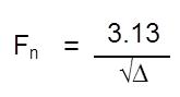
- The most important reason for limiting deflection is to make the pipe stiff enough, that is, of high enough natural frequency, to avoid a large amplitude response under any slight perturbing force. As a rough rule, for average piping, a natural frequency of 4 cycles per second will be found satisfactory. The natural frequency can be calculated by
3. Indentation
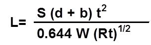
Where,
- t=corroded Thickness of pipe Wall(mm)
- S=0.67Sh(N/mm^2)
- R=Radius of pipe (mm)
- d=Bearing Length(mm)
- b=Bearing width(mm)
4. Allowable Load at Support
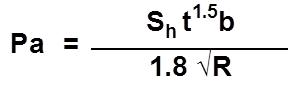
Where,
- Pa=Allowable Load at the Support point
- t=effective local thickness (pipe wall +Reinforced Pad If Any)
- R=outer radius of Pipe
- b=Bearing length of pipe (along the axis) on the support structure
IF THE ACTUAL LOAD AT SUPPORT IS GREATER THAN THE ALLOWABLE LOAD GIVEN BY THE ABOVE FORMULA, A REINFORCEMENT PAD WILL BE REQUIRED.
5. Vibration Possibility
The support span for vibration-prone lines is reduced to make the system stiffer such that the pipe does not easily vibrate. The natural frequency of the system is usually maintained above 4 Hz as mentioned in clause C.2 above.
D. Pipe Support Span Chart
A pipe support span chart is a table or diagram that provides information on the maximum allowable span for different types of piping and support configurations. The span is the distance between two points where a pipe is supported, such as at two adjacent pipe hangers.
The purpose of a pipe support span chart is to help engineers and designers ensure that piping systems are properly supported to prevent sagging, bending, or other types of stress that could cause damage or failure. By referring to the span chart, designers can select the appropriate type and spacing of supports for a given piping configuration, based on the materials used, the size and weight of the pipes, the fluid being transported, and other factors.
Pipe support span charts may also include information on the recommended type of support for different piping materials, such as steel, copper, or plastic, as well as information on recommended hanger spacing, temperature limits, and other design considerations. Proper use of a pipe support span chart can help ensure that piping systems are safe, reliable, and long-lasting.
Normally project-specific Support Span is provided in tabular format for straight pipes that are known as a “Pipe Support Span Chart”. But for elbows or turns, the span is to be reduced by a factor as shown in the attached figure (Fig. 2). Readymade support spans for specific pipe diameters and thicknesses are available in the MSS code. For the Shell group of companies, the support span is provided in DEP in tabular format.
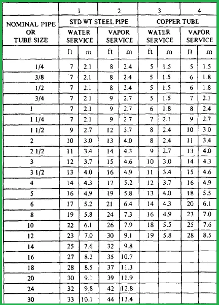
1. Pipe Support Spacing Chart for Steel Piping as per MSS-SP-69
A pipe support span chart is a tabular chart giving a rough idea of supporting distance. These charts are normally mentioned in piping stress analysis project specifications. In the following image (Fig. 3) pipe support span chart from MSS SP-69 is reproduced as a sample.
2. Pipe Support Spacing Chart for Steel Piping Based on ASME B31.1
The pipe support span as per ASME B31.1 for Steel piping is provided below:
| NPS (Inches) | DN (mm) | Water/ Liquid Service (m) | Water/ Liquid Service (ft) | Steam, Gas, Air Service (m) | Steam, Gas, Air Service (ft) |
| 1 | 25 | 2.1 | 7 | 2.7 | 9 |
| 2 | 50 | 3.0 | 10 | 4.0 | 13 |
| 3 | 80 | 3.7 | 12 | 4.6 | 15 |
| 4 | 100 | 4.3 | 14 | 5.2 | 17 |
| 6 | 150 | 5.2 | 17 | 6.4 | 21 |
| 8 | 200 | 5.8 | 19 | 7.3 | 24 |
| 12 | 300 | 7.0 | 23 | 9.1 | 30 |
| 16 | 400 | 8.2 | 27 | 10.7 | 35 |
| 20 | 500 | 9.1 | 30 | 11.9 | 39 |
| 24 | 600 | 9.8 | 32 | 12.8 | 42 |
General Notes for Table 1:
- This support span is valid for horizontal straight runs of standard and heavier steel pipe at a maximum operating temperature of 750°F (400°C).
- This support spacing chart does not apply in the presence of concentrated loads between supports, such as flanges, valves, and specialties.
- The pipe support spacing is based on a fixed beam support with a bending stress limiting to 2,300 psi (15.86 MPa) and insulated pipe filled with water or the equivalent weight of steel pipe for steam, gas, or air service, and the pitch of the line is such that a sag of 0.1 in. (2.5 mm) between supports is permissible.
3. Pipe Support Span Chart as per ASME B31.3
Process piping code ASME B31.3 does not provide any span chart for steel piping systems. Users usually develop their pipe support spacing table considering parameters like allowed stress, deflection, etc. A typical pipe support span for process piping for carbon steel and stainless steel pipe material is provided below (Reference: Shell DEP) in Table 2 and Table 3.
3.1 Pipe Support Span for Carbon Steel
| Vapour service | Liquid service | |||
| Pipe size | Bare | Insulated | Bare | Insulated |
| DN 15 (NPS ½) | 900 mm (3 ft) | 800 mm (2 ½ ft) | 900 mm (3 ft) | 800 mm (2 ½ ft) |
| DN 20 (NPS ¾) | 1400 mm (4 ½ ft) | 1200 mm (3.9 ft) | 1400 mm (4 ½ ft) | 1200 mm (3.9 ft) |
| DN 25 (NPS 1) | 3600 mm (11.8 ft) | 2300 mm (7.5 ft) | 3450 mm (11.3 ft) | 2250 mm (7.3 ft) |
| DN 40 (NPS 1 ½) | 3600 mm (11.8 ft) | 3000 mm (9.8 ft) | 3450 mm (11.3 ft) | 2800 mm (9.1 ft) |
| DN 50 (NPS 2) | 3600 mm (11.8 ft) | 3450 mm (11.3 ft) | 3450 mm (11.3 ft) | 3300 mm (10.8 ft) |
| DN 80 (NPS 3) | 6550 mm (21.4 ft) | 4600 mm (15 ft) | 5450 mm (17.8 ft) | 4200 mm (13.7 ft) |
| DN 100 (NPS 4) | 7500 mm (24.6 ft) | 5550 mm (18.2 ft) | 6100 mm (20 ft) | 4900 mm (16 ft) |
| DN 150 (NPS 6) | 9150 mm (30 ft) | 6800 mm (22.3 ft) | 7100 mm (23.2 ft) | 5800 mm (19 ft) |
| DN 200 (NPS 8) | 10500 mm (34.4 ft) | 8050 mm (26.4 ft) | 7950 mm (26 ft) | 6700 mm (21.9 ft) |
| DN 250 (NPS 10) | 11800 mm (38.7 ft) | 9050 mm (29.6 ft) | 8700 mm (28.5 ft) | 7400 mm (24.2 ft) |
| DN 300 (NPS 12) | 12900 mm (42.3 ft) | 9800 mm (32.1 ft) | 9150 mm (30 ft) | 7800 mm (25.5 ft) |
| DN 350 (NPS 14) | 15150 mm (49.7 ft) | 11850 mm (38.8 ft) | 10850 mm (35.5 ft) | 9300 mm (30.5 ft) |
| DN 400 (NPS 16) | 16250 mm (53.3 ft) | 12850 mm (42.1 ft) | 11200 mm (36.7 ft) | 9750 mm (31.9 ft) |
| DN 450 (NPS 18) | 17250 mm (56.5 ft) | 13750 mm (45.1 ft) | 11500 mm (37.7 ft) | 10150 mm (33.3 ft) |
| DN 500 (NPS 20) | 18200 mm (59.7 ft) | 14450 mm (47.4 ft) | 11750 mm (38.5 ft) | 10400 mm (34.1 ft) |
| DN 600 (NPS 24) | 18950 mm (62.1 ft) | 16050 mm (52.6 ft) | 12150 mm (39.8 ft) | 10950 mm (35.9 ft) |
| DN 750 (NPS 30) | 21000 mm (68.9 ft) | 17500 mm (57.4 ft) | 13100 mm (43 ft) | 11500 mm (37.7 ft) |
| DN 900 (NPS 36) | 22700 mm (74.5 ft) | 18500 mm (60.7 ft) | 13700 mm (45 ft) | 12500 mm (41 ft) |
| DN 1050 (NPS 42) | 23400 mm (76.8 ft) | 19500 mm (64 ft) | 14300 mm (47 ft) | 13000 mm (42.6 ft) |
| DN 1200 (NPS 48) | 25000 mm (82 ft) | 20500 mm (67.2 ft) | 14600 mm (48 ft) | 13400 mm (44 ft) |
3.2 Pipe Support Span for Stainless Steel
| Vapour service | Liquid service | |||
| Pipe size | Bare | Insulated | Bare | Insulated |
| DN 25 (NPS 1) | 2200 mm (7.2 ft) | 1800 mm (5.9 ft) | 2100 mm (6.8 ft) | 1800 mm (5.9 ft) |
| DN 40 (NPS 1 ½) | 2800 mm (9.1 ft) | 2500 mm (8.2 ft) | 2400 mm (7.8 ft) | 2500 mm (8.2 ft) |
| DN 50 (NPS 2) | 2800 mm (9.1 ft) | 2600 mm (8.5 ft) | 2700 mm (8.8 ft) | 2600 mm (8.5 ft) |
| DN 80 (NPS 3) | 6400 mm (21 ft) | 4050 mm (13.2 ft) | 4950 mm (16.2 ft) | 3500 mm (11.4 ft) |
| DN 100 (NPS 4) | 6400 mm (21 ft) | 4800 mm (15.7 ft) | 5300 mm (17.3 ft) | 4000 mm (13.1 ft) |
| DN 150 (NPS 6) | 9400 mm (30.8 ft) | 5750 mm (18.8 ft) | 5950 mm (19.5 ft) | 4600 mm (15 ft) |
| DN 200 (NPS 8) | 10750 mm (35.2 ft) | 6800 mm (22.3 ft) | 6450 mm (21.1 ft) | 5200 mm (17 ft) |
| DN 250 (NPS 10) | 10750 mm (35.2 ft) | 7600 mm (24.9 ft) | 6950 mm (22.8 ft) | 5650 mm (18.5 ft) |
| DN 300 (NPS 12) | 10750 mm (35.2 ft) | 8250 mm (27 ft) | 7350 mm (24.1 ft) | 6050 mm (19.8 ft) |
| DN 350 (NPS 14) | 10750 mm (35.2 ft) | 8700 mm (28.5 ft) | 7600 mm (24.9 ft) | 6300 mm (20.6 ft) |
| DN 400 (NPS 16) | 11000 mm (36 ft) | 9450 mm (31 ft) | 7750 mm (25.4 ft) | 6550 mm (21.4 ft) |
| DN 450 (NPS 18) | 11000 mm (36 ft) | 9700 mm (31.8 ft) | 7850 mm (25.7 ft) | 6750 mm (22.1 ft) |
| DN 500 (NPS 20) | 11500 mm (37.7 ft) | 10500 mm (34.5 ft) | 8400 mm (27.5 ft) | 7300 mm (23.9 ft) |
| DN 600 (NPS 24) | 12000 mm (39.3 ft) | 11000 mm (36 ft) | 9050 mm (29.6 ft) | 8050 mm (26.4 ft) |
| DN 750 (NPS 30) | 14000 mm (45.9 ft) | 13000 mm (42.6 ft) | 10500 mm (34.5 ft) | 9500 mm (31.2 ft) |
| DN 900 (NPS 36) | 16000 mm (52.5 ft) | 15000 mm (49.2 ft) | 11500 mm (37.7 ft) | 10500 mm (34.5 ft) |
| DN 1050 (NPS 42) | 18000 mm (59 ft) | 16500 mm (54 ft) | 12500 mm (41 ft) | 11500 mm (37.7 ft) |
| DN 1200 (NPS 48) | 20000 mm (65.6 ft) | 17300 mm (56.8 ft) | 13500 mm (44.3 ft) | 12500 mm (41 ft) |
E. HDPE Pipe Support Span
The maximum allowable span for HDPE pipes will depend on various factors, such as the pipe size, wall thickness, and temperature of the fluid being transported. In general, HDPE pipes require more support than steel pipes due to their flexibility and low modulus of elasticity.
The Plastics Pipe Institute (PPI) provides guidelines for designing supports for HDPE pipes, which includes recommendations for maximum allowable span. According to PPI, the maximum allowable span for HDPE pipes should not exceed the following:
- 4 feet for 1-inch diameter pipes
- 5 feet for 1.25-inch diameter pipes
- 6 feet for 1.5-inch diameter pipes
- 7 feet for 2-inch diameter pipes
- 9 feet for 3-inch diameter pipes
- 11 feet for 4-inch diameter pipes
- 13 feet for 6-inch diameter pipes
- 15 feet for 8-inch diameter pipes
- 18 feet for 10-inch diameter pipes
- 22 feet for 12-inch diameter pipes
However, it is important to note that these are general guidelines and the actual span may vary depending on the specific application and the design criteria used. It is always recommended to consult with a qualified engineer or piping designer to determine the appropriate support span for a specific HDPE piping system.
F. GRE Pipe Support Span
The maximum allowable span for Glass Reinforced Epoxy (GRE) pipes will depend on various factors, such as the pipe diameter, wall thickness, and the type of fluid being transported.
The Fiberglass Reinforced Plastic Institute (FRPI) provides guidelines for designing supports for GRE pipes, which includes recommendations for maximum allowable span. According to FRPI, the maximum allowable span for GRE pipes should not exceed the following:
- 2 feet for 1-inch diameter pipes
- 2.5 feet for 1.25-inch diameter pipes
- 3 feet for 1.5-inch diameter pipes
- 4 feet for 2-inch diameter pipes
- 6 feet for 3-inch diameter pipes
- 7 feet for 4-inch diameter pipes
- 8 feet for 6-inch diameter pipes
- 10 feet for 8-inch diameter pipes
- 12 feet for 10-inch diameter pipes
- 14 feet for 12-inch diameter pipes
It is important to note that these are general guidelines and the actual span may vary depending on the specific application and the design criteria used. It is always recommended to consult with a qualified engineer or piping designer to determine the appropriate support span for a specific GRE piping system.
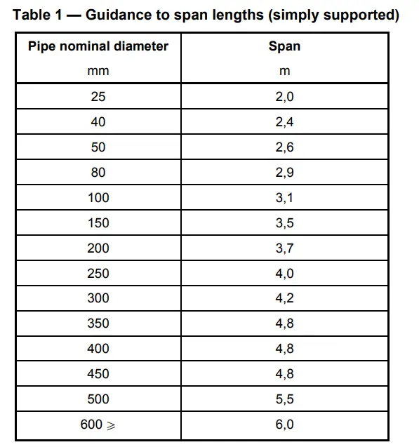
ISO 14692-2002 also provides a typical GRE pipe support span table to be used for FRP/GRE pipes in Table 1 (The same is reproduced below in Fig. 4).
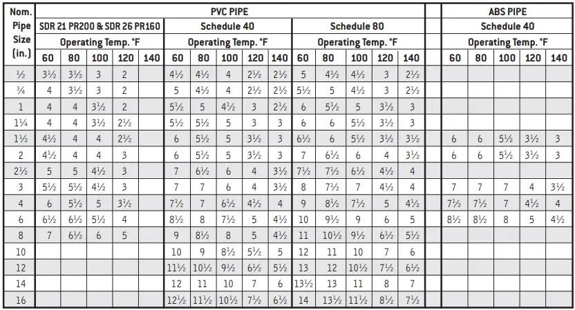
G. ABS and PVC Pipe Support Spacing
PVC and ABS pipe support spacing is mainly based on the manufacturer. The following image (Fig. 5) provides some typical values for ABS and PVC Pipe Support Spans.
H. Online Video Courses on Piping Support
To learn more about piping support design and engineering you can opt for the following video course.
hi all,
with respect to Pa (allowable load at spport) where Sh is “hot allowable stress” or “Bending stress got from caesar software”
ost but I was wanting to know if you could write a litte more on this subject? I’d be very thankful if you could elaborate a little bit more. Thanks!
pl.give sample deflection calculations with applicable formula.
I want this documents.Please send me.
Thk.
Pipe span we will calculate based on which allowable stress, which is defined in ASME B31. 3.
I want more details for manual calculation for pipe stress or force calculation. Do you have any reference please share
Question,
i have 12 dia. Schedule 10 Stainless Steel pipe. this is only air going thru the pipe at approx. 250 deg. F.
I am supporting this above ground and would like to support approx. 30 feet only one section.
I can not find any information about supporting Sch. 10 Stainless Steel Pipe. Can you give me any assistance
Normally for 10s and 5s pipe wall supporting to be do with pipe indentations calculations.
Due to thin wall thickness it will fail with pipe loading..
There is a Kellogg method to be used to do it.
If u increase the contact area of piping to resting support steel will pass the stress values of pipe support points
Excellent article.
One point of discussion, the max deflection of a pipe.
Many years ago I was asked the question and during research I found an old standard, which limited the deflection by measuring the angle of the pipe to the horizontal at the support point. Assuming a 1:100 fall between supports, if the angle was less than zero then there would be a risk of pockets in the pipe. I know that this is not critical for many situations but it gave a rational reason for the deflection values.
what is the significance of L/600 in calculating pipe supports and its derivation
hi
can you provide me with some reference calculations or procedures for the pipe support member size selection?
Regards
Yogender
ID yogi1111thakur@gmail.com
Hello Anup, my name is Dennis – I am an Electrical Engineer working on Fleet scale EV charger deployments – can you (or can you refer me to a Piping Engineer consultant) and help me design a tubular racking structure that I can erect in parking lots to hang EV chargers. Ideally, I want 12-ft or 24-ft spans between my posts – from your table above I think 8″ pipe would work. Any help with be most appreciated.
Thanks for share information. Blessing for you
Please can you advise the following:
For allowable load at supports formula, there is no definition for Sh. Please advise.
Is this allowable formula for the middle spans?
What would be applied forces at the bends for pipes above ground? How about applied forces for the middle supports to be considered?
Please can you provide references to your formulae.
Thanks in advance.
Taghi
Hi,
Do you have the reference for the Indentation formula you have used please?
Best regards,
John
Hi Anup,
I need a reference for the Indentation formula stated in your blog.
Can you please send me the reference details?
Best regards,
John