
What is Acoustic-Induced Vibration or AIV?
Acoustic-Induced Vibration or AIV is a severe high-frequency vibration that the piping systems carrying vapor or gases may experience near the high-pressure-reducing devices. Due to high-pressure drops of vapor/gas services in this pressure-reducing device like a relief valve, orifice plate, control valve, depressuring valve, Choke Valve, Blow Down valve, etc, a high-frequency sound wave in the range of 500–2,000 Hz is generated. This wave energy induces vibration (and stress) and excites the pipe wall in the circumferential direction causing radial pipe displacement and eventually acoustic fatigue failure within a very short period of time (A few minutes or hours). Piping components with high-stress concentration zones like pipe fittings, small-bore pipe connections, Fabricated tee, welded pipe supports, etc are prone to such acoustic-induced vibration failures.
Since the high viscosity of liquid or two-phase fluid dampens the circumferential pipe displacements, Acoustic Induced Vibration or AIV is not a concern for such systems.
Cause of Acoustic Induced Vibration
There are two main causes for Acoustic Induced Vibration (AIV), they are:
- high-pressure drops and
- high flow rates in vapor/gas services
Mechanism of Acoustic Induced Vibration (AIV)
In Acoustic Induced Vibration, the high-velocity fluid impingement on the piping wall, turbulent mixing, and shockwaves downstream of the flow restriction give rise to a high level of noise. This noise level is a function of pressure drop across the pressure-reducing device and gas/vapor mass flow rate. The noise is transmitted downstream of the flow restriction losing energy to friction, work is done by vibrating the pipe, and heat is lost to the surroundings. A noise or sound level of 155 dB is considered a safe level when the circumferential vibration is no longer a concern. Industry standards and experience show acoustic energy attenuates 3 dB for every 50D of piping from the source. The response caused by high-frequency acoustic excitation affects the piping downstream of the source to the first major vessel, i.e, the Separator, KO drum, etc.
Screening for Acoustic Induced Vibration
Design Engineering Practice (DEP) by Shell Global Inc provides rules for screening the systems for Acoustic Induced Vibrations (AIV). To study the effect of AIV on the piping system it is required to calculate the sound power level at the concerned pressure-reducing device based on the following equation:
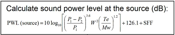
Where:
- P1 is upstream pressure (bara)
- P2 is downstream pressure (bara)
- W is the flow rate (kg/s)
- T is the upstream temperature (K)
- Mw is molecular weight (grams/mol)
- SFF is a correction factor to account for multiple occurrences of sonic flow in a line. If consecutive sonic conditions exist, then SFF=6; otherwise SFF = 0.
All the above-mentioned data can be received from the Process engineering team. If the calculated Sound power level is less than (or equal to) 155 dB, then there is no concern from the AIV viewpoint. However, if the calculated Sound power Level is more than 155 dB, then the LOF (Likelihood Of Failure) value needs to be calculated following the steps provided by Energy Institute guidelines for the avoidance of vibration-induced fatigue failure in process pipework.
Mitigation of AIV
Considerations for Acoustic Induced Vibration mitigation must be done during the design stage of the project as failures in AIV can happen within minutes of operation. There are various options for AIV mitigation. However, the following options are the most common:
- Using a higher pipe schedule or lowering the D/t ratio.
- Decreasing flow velocity by increasing pipe diameter.
- Using smoother pipe fittings ensures a smooth transition from the branch to the main header.
- Using Clamp-on supports and stiffening rings.
- Using a full wrap-around pad on welded pipe supports. Full wrap-around is more commonly accepted in industry standards than partial reinforcing.
- Using Multi-Stage Pressure Drop Internal Trim (Low noise trim) to reduce noise levels at the valve.
- Using In-line Acoustic Silencer downstream of a pressure-reducing valve will reduce the acoustic energy near its origin point and prevent its further propagation. However, as silencers themselves are susceptible to mechanical damage from high acoustic energy exposure, this is not suggested.
- Increasing line length between acoustic-induced vibration source and high-risk stress concentrated locations
Attenuation of acoustic energy at the source is the most preferred approach to achieve acceptable sound power energy in a piping system if the same is physically and economically feasible. Two types of devices can accomplish this:
Low Noise Control Valves:
As the acoustic energy generated due to turbulent fluid stream is highly sensitive, valve manufacturers design valves to generate lower levels of acoustic energy, known as low noise control valves. Depending on the sound power energy attenuation requirement of the system various design options are available:
- Multipath Design with special low-noise trim.
- Staged Trim design
- Labyrinth Disk design
Restriction Orifice:
The acoustic energy generated at the source can be controlled by a multi-stage restriction orifice. One-stage pressure let-down systems operate at choked flow conditions generating extremely high levels of acoustic energy. This causes increased turbulence and shock waves downstream. Installing a series of restriction orifices (multi-stage) downstream of the let-down valve will attenuate this acoustic energy. Using multiport expansion plates in restriction orifice design is also an alternate option for mitigating acoustic-induced vibration.
If reducing the generated acoustic energy is not feasible, finding options to reduce the level of resonant response can be considered. Steps must be considered to dampen the vibration amplitude or to improve the mechanical integrity of the piping system by reducing stress concentrations.
System damping can be increased by using anti-vibration materials (elastomer). Stress concentrations can be reduced by
- increasing pipe thicknesses
- using full-wrap reinforcements
- using standard branch connections (Welding Tee, Olets, etc) in place of un-reinforced fabricated connections
- Removing screwed fittings
- eliminating branches 2 inches and smaller
- avoiding abrupt geometric changes in line.
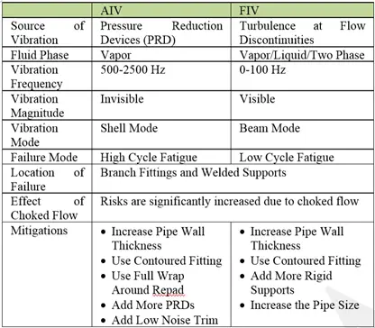
Comparison of FIV and AIV
The following image shows the comparison between Flow Induced and Acoustic Induced Vibrations in a Piping System
Few more related Resources for you.
What is Acoustic-Induced Vibration or AIV?
What is Flow-Induced Vibration (FIV) in a Piping System
Basics of Vibration Monitoring: A Presentation
Motion Amplification Technology (MAT) for Piping Vibration Visualization
Common Causes and Effects of Piping Vibration
Solving vibration problems in a two-phase flowline by Dynaflow Research Group
Considerable points while installing centrifugal pumps at the site to reduce vibration
References and Further Study
- Energy Institute guidelines for the avoidance of vibration-induced fatigue failure in process pipework
- https://www.bechtel.com/getattachment/Blog/technical/October-2019/Differentiating-Between-Acoustic-and-Flow-Induced/Differentiating-Between-Acoustic-and-Flow-Vibrations.pdf
- DEP 31.38.01.26 V43
Regarding the AIV in high pressure control valve, we considered the following options as possible solutions: resizing the control valve or installing a restriction orifice downstream the control valve.
We experienced failures in the flange stud bolts of the control valve. We found vibration peaks at 4.1 kHz.
Mitigation of AIV
Using a full wrap-around pad on welded pipe supports. Full wrap-around is more commonly accepted in industry standards than partial reinforcing.
Why full wrap reinforcement accepted…???
Short answer:
For AIV, the modal interaction is circumferential, so a circumferential discontinuity (i.e. a partial reinforcement pad) would produce a stress raiser / stress intensification point.
I trust none of the counter jargon! If you used a freq of 440hz I bet it would work!!!!!!!!!!!!!!!!
moderation is what people tolerate, truth is truth, you can not deny it!!!!!!!!!!
Is it usually a requirement to also screen for FIV for piping downstream of relief valves? Noticed that FIV screening are done for normal flow lines, and not for relief lines. However, sometimes there are 2-phase relief lines as well. Appreciate your thoughts.