
Bracing Connections involve the bolting of flat, angle, channel, I-section, and hollow section members to a gusset plate to support the column or other members. The bracing member in a bracing connection can work in tension alone, or in both tension and compression and stabilize the main components by distributing the loads. In this article, we will explore the basics of bracing connections
Bracing connections serve as the backbone of many structural systems, providing lateral stability and helping resist forces like wind, seismic activity, and even the structural loads themselves. These connections transfer loads from the building or structure to the foundation, ensuring that it remains upright and safe even during extreme conditions.
Benefits of Structural Steel
Some benefits associated with the use of structural steel for owners are:
- Steel allows for reduced frame construction time and the ability to construct in all seasons
- Steel makes large spans and bay sizes possible, providing more flexibility for owners
- Steel is easier to modify and reinforce if architectural changes are made to a facility over its life
- Steel is lightweight and can reduce foundation costs
- Steel is durable, long-lasting, and recyclable
Unique Aspects of Steel Construction
Procurement and management of structural steel are similar to other materials, but there are some unique aspects to steel construction:
- Steel is fabricated off-site
- On-site erection is a rapid process
- This gives users of structural steel some scheduling advantages
- Coordination of all parties is essential for achieving potential advantages
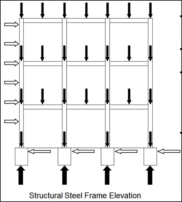
Forces on Structures
The structure will be subjected to various kinds of loads (Fig. 1) like
- Forces from gravity, wind, and seismic events are imposed on all structures
- Forces that act vertically are gravity loads
- Forces that act horizontally, such as stability, wind, and seismic events (the focus of this discussion) require lateral load-resisting systems to be built into structures
- As lateral loads are applied to a structure, horizontal diaphragms (floors and roofs) transfer the load to the lateral load-resisting system.
The type of lateral load-resisting system to be used in a structure should be considered early in the planning stage. Lateral stability and architectural needs must be met
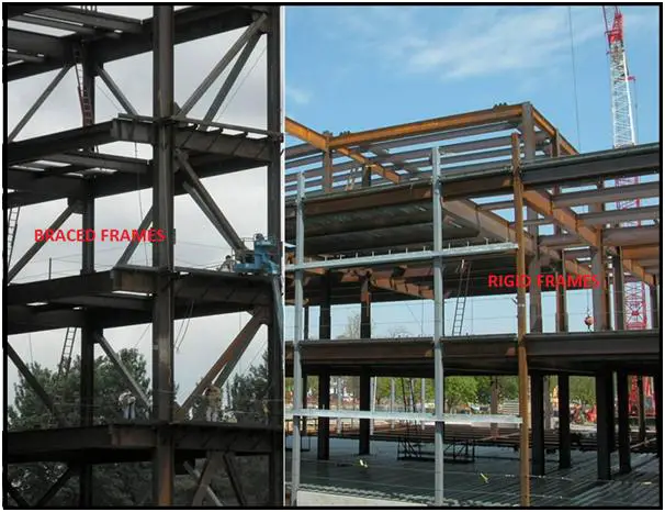
The three common lateral load-resisting systems are:
- Braced Frames (Fig. 2)
- Rigid Frames (Fig. 2)
- Shear Walls
Steel Frame Connection Types
- Simple Connections.
- Moment Connections: Fully Restrained and Partially Restrained.
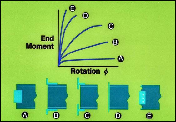
- All connections have a certain amount of rigidity.
- Simple connections (A above) have some rigidity but are assumed to be free to rotate.
- Partially-Restrained moment connections (B and C above) are designed to be semi-rigid.
- Fully-Restrained moment connections (D and E above) are designed to be fully rigid.
Simple Connections
- Designed as flexible connections.
- Connections are assumed to be free to rotate.
- Vertical shear forces are the primary forces transferred by the connection.
- Require a separate bracing system for lateral stability.
- The following few slides show some common simple framing connections.
Moment Connections
- Designed as rigid connections that allow little or no rotation, Used in rigid frames.
- Moment and vertical shear forces are transferred through the connection.
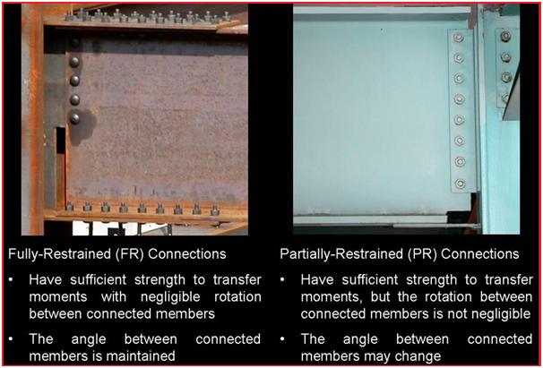
- Two types of moment connections are permitted: Fully-Restrained and Partially-Restrained (Fig. 4).
Rigid Frames
- Rigid frames, utilizing moment connections, are well suited for specific types of buildings where diagonal bracing is not feasible or does not fit the architectural design
- Rigid frames generally cost more than braced frames
Braced Frames
- Diagonal bracing creates stable triangular configurations within the steel building frame
- “Braced frames are often the most economical method of resisting wind loads in multi-story buildings.”
- Some structures, like the one pictured above, are designed with a combination of braced and rigid frames to take advantage of the benefits of both
Temporary Bracing
- Structural steel frames require temporary bracing during construction
- Temporary bracing is placed before plumbing up the structural frame
- This gives the structure temporary lateral stability
- Temporary bracing is removed by the erector
- In a braced frame, temporary bracing is removed after the final bolt-up is complete and the permanent bracing system is in place
- In a rigid frame, temporary bracing is removed after the final bolt-up is complete
Concentric Braced Frames
Bracing is concentric when the center lines of the bracing members intersect Common concentric braced frames used in buildings today include:
- Cross brace
- Two-story X’s
- Chevron
- Single diagonals
Cross-bracing design is possibly the most common type of braces. Bracing can allow a building to have access through the brace line depending on the configuration
Cross-Bracing Design Example
- The diagonal members of Cross bracing go into tension and compression similar to a truss.
- The multi-floor building frame elevation shown above has just one braced bay, but it may be necessary to brace many bays along a column line
- With this in mind, it is important to determine the locations of the braced bays in a structure early in a project
- Connections for X bracing are located at the beam-to-column joints
- Bracing connections may require relatively large gusset plates at the beam-to-column joint
- The restriction of space in these areas may have an impact on the mechanical and plumbing systems as well as some architectural features

Chevron Bracing
- The members used in Chevron bracing are designed for both tension and compression forces
- Chevron bracing allows for doorways or corridors through the bracing lines in a structure
- Chevron bracing members use two types of connections
- The floor-level connection may use a gusset plate much like the connection on X-braced frames
- The bracing members are connected to the beam/girder at the top and converge to a common point
- If gusset plates are used, it is important to consider their size when laying out mechanical and plumbing systems that pass through braced bays
Eccentrically Braced Frames
- Eccentric bracing is commonly used in seismic regions and allows for doorways and corridors in the braced bays
- The difference between Chevron bracing and eccentric bracing is the space between the bracing members at the top gusset connection
- In an eccentrically braced frame bracing members connect to separate points on the beam/girder
- The beam/girder segment or “link” between the bracing members absorbs energy from seismic activity through plastic deformation
- Eccentrically braced frames look similar to frames with Chevron bracing
- A similar V-shaped bracing configuration is used
Combination Frames
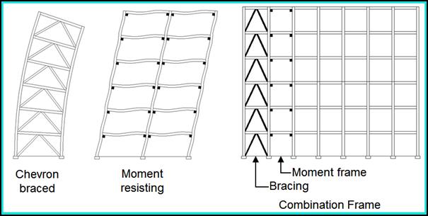
- As shown in Fig. 6 (left) a braced frame deflects like a cantilever beam while a moment-resisting frame deflects more or less consistently from top to bottom
- By combining the two systems, reduced deflections can be realized
- The combination frame is shown above right
Few more useful resources for you..
Structural Platforms: An In-Depth Guide
A Short Presentation on Pile Foundation and its Design
An article on Tank Pad Foundation
An Introduction to Braced Connections
A short article on “Sun Shade for oil and gas industry and their Design”
Considerations for Project Site Selection
Hi
I saw your blog . It is nice . I have one doubt .
How structure will understand tension bracing only command provided in design
If we are using pipe as tension bracing . Not cable or rod .
Can you please explain