
The term HIPS stands for ‘High Integrity Protection System’. In upstream Oil and Gas projects, HIPS is usually used for the protection of pipelines and associated equipment downstream of a production manifold, from an overpressure scenario, for example, due to a blocked outlet. Hence, HIPS is sometimes termed as HIPPS – ‘High Integrity Pressure Protection System’.
Simply told, HIPPS or high integrity pressure protection system is a highly reliable Safety Instrumented System (SIS) which, on detecting a high pressure, would cut off the pressure source to avoid damage to the downstream pipeline. In this article, we will use the term HIPPS in the above-specified context, though HIPPS may be used in other applications too.
As HIPPS, in effect, replaces the conventional pressure relief systems, the last safety barrier, it shall be extremely reliable, which means that the HIPPS shall be designed to achieve a high Safety Integrity Level (SIL). Implementation of HIPPS mandates stringent documentation, testing, and inspection plans.
HIPPS typically comprises of the following:
- Sensors- three Pressure Transmitters, configured in ‘two out of three (2oo3) voting logic
- Logic solver
- Final Elements – two high-integrity fast acting isolating valves
Typical Architecture of High Integrity Pressure Protection System
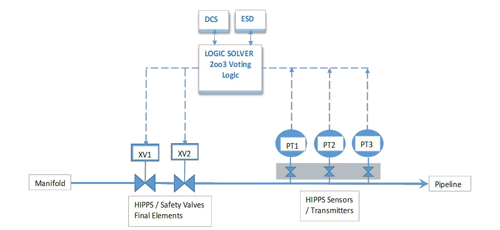
HIPPS sensors/initiators – Three Pressure Transmitters PT1, PT2, and PT3, measure the pressure downstream of HIPPS.
On detection of high pressure (at least two out of three transmitters measuring high pressure), the Logic Solver will initiate the close commands for both the isolating valves XV1 and XV2 (final elements). This action will cut off the pressure source and protect the downstream pipeline and equipment, which are designed for low pressure. Such a low-pressure system design could give significant project cost savings, owing to large pipe diameter and long pipeline lengths. The above safety loop can be termed as a Safety Instrumented Function (SIF).
Sensors – Pressure Transmitters
The transmitters shall have independent process taps/root isolation valves provided on the piping; shared isolation valves are not permitted. The transmitters shall be certified for use in SIL 3 application.
The project specifications may require special manifolds for the transmitters. Such manifolds are provided with a mechanical valve interlock to ensure that not more than one transmitter can be removed out of service for the purposes of testing or maintenance.
Similarly, it may be required to provide transmitters of different makes or models to reduce the possibility of common mode/ cause failure.
Where heat tracing is required for the pressure transmitter impulse tubing and manifold, the same shall be provided with reliable components, suitable alarms, and diagnostic features.
Logic Solver
The HIPPS logic solver is usually an independent SIL 3 certified Programmable Logic Controller (PLC), where the 2oo3 high-pressure voting and isolation valve trip logic is executed. However, sometimes this logic can also be executed in the plant’s emergency shutdown system (ESD), subject to satisfying the requirements of the required SIL.
The HIPPS PLC shall be supplied complete with redundant Processors, IO modules, Power supplies, Communication modules, operator interface, local printer, system, and application software, cabinet, wiring, and interface with the plant control system as per the project specifications.
HIPPS Valves
The HIPPS valves shall be high-performance, quick-closing, tight shut-off, fail-closed Isolation Valves. SIL certificates/reliability data of the valves shall be provided by the valve vendors.
Two HIPPS valves shall be installed in series. It may be required that the valves be of different types, to avoid common modes of failure, like valves stuck at their open position.
The HIPPS valves shall utilize Instrument air as the medium for actuation. Usually, volume bottles with backup Instrument air are provided to ensure high availability. Where Instrument air is not available, like remote well pads, hydraulic oil can be used. Redundant hydraulic oil pumps and oil headers shall be used to avoid common mode failure of the hydraulic system.
If the valves are located within the fire zone, necessary fireproofing of the valve actuators, Instrument air volume bottle, or the hydraulic power unit (HPU) shall be considered.
Valve leakage, the material of construction, and other features shall be as per the Valve Datasheet. The valve closing time required shall be determined from the simulation study and the same shall be recorded in the datasheet.
HIPPS valves shall be provided with “smart” positioners to facilitate periodic and remote partial and full stroke testing.
HIPPS Interfaces
The HIPPS shall be provided with a redundant serial communication link with the Distributed Control System (DCS) and a hardwired connection with the ESD system for information exchange.
Following are the typical interfaces with the DCS / ESD:
- Interlocks with plant on HIPPS actuation
- ‘Reset’ / Opening of HIPPS valves once the trip initiators are healthy
- Graphic interface to the plant operator showing the status of HIPPS
- The sequence of Events (SOE), alarms, and HIPPS diagnostics,
- Time synchronization
- Reporting and printing
HIPPS can be supplied complete as a package, with all the components described above, by a single vendor/integrator. Alternatively, the EPC Contractor may source the various components from different suppliers. In both cases, the complete system shall be certified for the desired SIL.
Safety Integrity Level (SIL)
The criticality of a Safety Instrumented Function (SIF) is expressed in SIL classes 1 to 4 as per IEC 61508. SIL defines the target ‘Probability of Failure on Demand (PFD) or a target level of Risk Reduction. The Risk Reduction Factor (RRF) is defined as follows:
RRF = 1 / PFD
A SIL 1 safety function provides minimum Risk Reduction (RRF 10 to 100 times), has the highest Probability of Failure on Demand (PFD), and is considered the least reliable.
A SIL 4 safety function provides maximum Risk Reduction (RRF 10,000 to 100,000 times), has the lowest Probability of Failure on Demand (PFD), and is considered the most reliable.
The target SIL of the HIPPS is defined by the SIL assessment team in a SIL assessment workshop. HIPPS shall be designed to achieve or exceed the target SIL, typically SIL 3. This is achieved by using redundant design, with no common mode failure, having good diagnostics, and performing periodic testing of all the elements.
For example, to meet the SIL 3 requirements, the HIPPS shall have a PFD value between 10-3 and 10-4 which may be achieved by using the following configuration:
- Initiators – three pressure transmitters in a 2oo3 voting configuration
- Logic solver – an independent PLC
- Final elements – two isolation valves installed in series
All the above components shall be certified for use in a SIL 3 safety loop.
Once the HIPPS transmitters, PLCs, and valves are finalized for ordering, the reliability data of these elements shall be obtained from the respective suppliers to perform the PFD calculations and to verify if the HIPPS is meeting the target SIL.
The Safety Requirement Specification (SRS) compiles all the data related to the HIPPS, such as the overpressure scenario details, the mitigation method, functional logic narratives, dynamic simulation recommendations, the target SIL, process safety time, proof test intervals, the HIPPS configuration and response time to achieve the target SIL, etc.
HIPPS response time shall be sufficient to prevent the overpressure scenario.
HIPPS response time = Response time of the initiators + (IO data processing time + scan time) of the logic solver + Valve opening time
Testing of HIPPS Elements
All the elements of HIPPS shall be proof tested at defined internals as defined in the SRS or as considered while calculating the PFD, to ensure maintain the validity of the loop SIL certification.
The typical test intervals may be as follows:
- Logic Solver – 36 months
- HIPPS valves – full stroke testing – 24 months, partial stroke testing – 3 months
- Pressure Transmitters – 24 months