
A plot plan is a key engineering document of the engineering phase. The plot plan schematically locates the equipment layout, the position of roads, buildings, support infrastructures, and other constructions inside an industrial plant with their dimensions and distances in between. The plot plan is a vital document as it serves as the basis for establishing the sequence of major engineering and construction activities.
Plot plans are usually initiated in the pre-contract, conceptual, and development stages of a proposal. During the detailed engineering phase, as the project progresses, they are developed with proper information and dimensions. Even though the plot plans are used by every engineering group, the plot plan is developed by the plant piping layout engineers/designers. The plot plan is a dynamic document and keeps evolving throughout the project life.
Definition of a Plot Plan Drawing
A plot plan drawing can be defined as a master plan drawing locating each unit/facility within the plot boundary. It shows the arrangement of equipment and supporting facilities to integrate any process within a common battery limit area. The plot plan drawing usually identifies all items using proper number designation and draws the basic shapes to the scale. It basically provides a bird’s eye view of the full property.
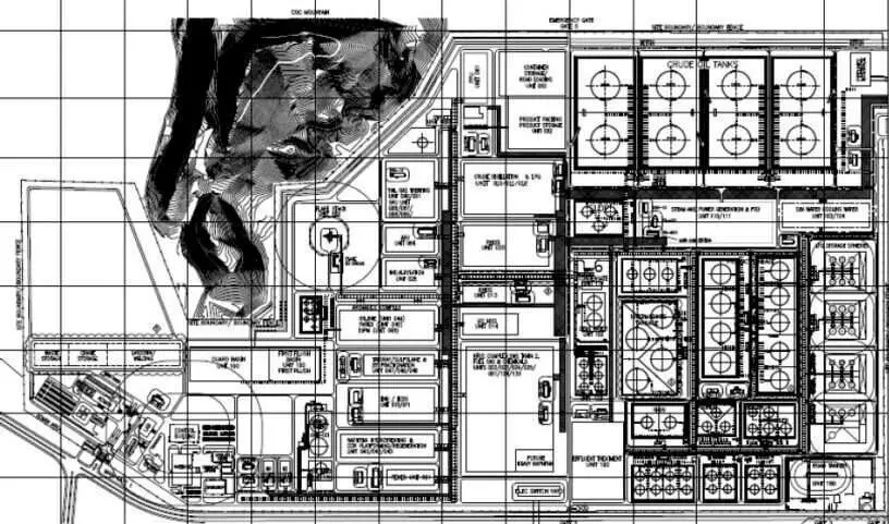
Fig. 1 below shows an example of a typical plot plan for a plant.
Applications of Plot Plan Design
The applications of a plot plan are manifold. The plot plan document is by all engineering departments executing the project for various purposes as listed below:
- The piping team uses the plot plan drawing to produce equipment arrangement studies, optimize the pipe and equipment route philosophy within a limited area, and get an initial estimate of piping material quantities.
- The civil team uses the plot plan to develop foundations for support design, grading, drainage plans, diked areas, holding ponds, structural designs, and all bulk material estimates for preliminary design.
- The electrical engineering team uses the plot plan for locating substations, switchgear, motor control center, etc to cable routing and to have a preliminary estimate of bulk materials.
- The instrumentation team utilizes the plot plan for deciding the location of the main control house, analyzer houses, and cable trays and to get a rough estimate of bulk materials.
- The plot plan is used by process engineers for initial hydraulic design, line sizing, and utility block flow requirements.
- The planning and Scheduling team uses the plot plan to plan and schedule the orderly completion of the engineering design.
- Throughout the entire construction phase, the construction team uses the plot plan to study and determine the erection sequence of all equipment, constructibility reviews, and laydown areas.
- Project and Estimation engineers use the plot plan is used to determine the overall cost of the project.
- And finally, the client uses the plot plan to perform safety, operation, and maintenance reviews and to develop an as-built record of the plant arrangement.
- Plot plan drawings are key documents to assess fire protection and are thus used as an essential document for permits and determining environmental and personnel safety.
Types of Plot Plan Drawings
In general, a plot plan for any project is divided into two groups:
- Overall Plot plan for all the units of the project combined and
- Unit Plot Plan for each separate unit.
However, there are various other terms that are sometimes used to provide an example of plot plans like:
- Proposal plot plan for establishing the bid document.
- Sectional Plot Plan where the plot plan is broken down into manageable-sized drawings.
- Planning plot plan to start initial work by all engineering teams.
- Production plot plan as the basic document for detailed design work.
- Construction plot plan to start erection and construction work at the site.
- As-built plot plan in the final plot plan reflecting the completed project as constructed.
Inputs Required for Plot Plan Development
Plot Plan development is very important to produce a safe, cost-effective operational plant. Plot plans are developed in stages as and when updated information is available. Developing an error-free plot plan requires knowledge of plant layout requirements, maintenance, and operational access requirements. Various inputs are required during plot plan drawing development. Some of those inputs are:
- Equipment list with a number designation
- Process flow diagram or PFD indicating how each piece of equipment is interconnected.
- Block flow diagram indicating interconnecting lines between storage facilities, process plants, and utility plants.
- Specifications indicating clearances, spacing, access, and maintenance requirements.
- Existing site map mentioning geographic details like plant elevation datum, reference coordinates, weather conditions, available real estate, road, railroad, river, and land contours, etc.
- Preliminary size/drawing of each piece of equipment.
- Requirement of critical piping materials.
- Preliminary civil drawings for structures and buildings.
- Preliminary pump house, compressor house, substation, and control room layout.
- Preliminary pipe rack information.
- Underground facilities.
- Plant raw material entry.
- Approach to main plant entry.
- Prevailing wind direction.
- Product despatch and transportation.
- Utility requirements.
- Area topography contour map.
- Any client-specific requirements.
Information Contained in a Plot Plan Drawing
A Plot Plan drawing is usually printed on the standard A1 sheet. The common information that a plot plan drawing usually provides are:
- Plant base coordinates in true Northing and Easting.
- Individual plants with their boundary co-ordinates & grade elevations
- Well locations
- Roads with centerline coordinates & width, boundary walls
- Geographical north, plant north, wind direction
- Existing plant details for correlation
- Location of major pipe bridges.
- Boundary coordinates for Plant Areas with the designation.
- Fences, gates, and Escape routes.
- Plant and Non-plant Buildings.
- All main equipment (including skid-mounted units)
- Package items & assemblies, skid-mounted consoles, etc.
- Pipe rack main supports.
- Pipe bridges.
- Electrical and instrument cable trays.
- Sterile areas around flares, vents, and burn pits.
- All major operating platforms, walkways, and stairs.
- Benchmarks indicating coordinates and elevation.
- Grade Elevation.
- True north and Plant north with included angle at the right-hand top corner.
- Prevailing wind direction.
- Earthling and cathodic protection wells.
- Bund walls.
- The main equipment list indicated on the plot plan.
- Eye wash\safety showers & utility station.
- All roads and access ways.
- Maintenance spaces, drop areas, and tube pull-out areas.
- Overhead cranes, monorails, EOT cranes, etc.
- Explanation of all abbreviations and symbols used in the drawing.
How we make plot plan .?
Please provide interview based important questions for better preparation.
Having higher experience hence they expect more.
Please explain the difference between off-plot and on-plot.
In a plot plan, which areas are on-plot and which ones are off-plot?
This question is for off-site & on-site too?
For on plot ref ASME B31.3 (related to process piping system )
& off plot ref. ref API 1104 ( related to hydrocarbon piping system)