
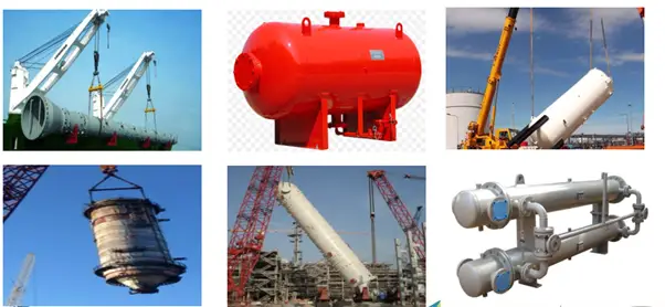
A Lifting lug is a plate with a hole in it. As the term specifies, lifting lugs are used for lifting. The hole is sized to fit a clevis pin. Using lifting lugs combined with the clevis pins, loads are transferred from one mechanical component to another. For mechanical static equipment (Fig. 1), these lifting lugs are used by cranes for transportation and installation.
While lifting this mechanical equipment, the lugs must be able to carry the complete weight of the equipment. Also, while transporting and installing various kinds of forces act on those lifting lugs. Hence, the lifting lug design has to be accurate enough to avoid any failure. In this article, we will briefly explore the lifting lug design methodology.
Types of Lifting Lugs
Lifting lugs are commonly used in process industries to facilitate the safe and efficient lifting and transportation of heavy equipment and components. Here are some common types of lifting lugs used in process industries:
- Fixed lugs: Fixed lugs are permanently attached to the equipment or component and are designed to provide a secure lifting point. Fixed lugs are typically welded or bolted to the equipment and are load rated to ensure they can safely support the weight of the equipment.
- Swivel lugs: Swivel lugs are designed to rotate around a central axis, which allows the lifting force to be evenly distributed and reduces the risk of the equipment or component twisting or turning during lifting. Swivel lugs can be fixed or removable and are often used in conjunction with spreader bars to lift large or irregularly shaped equipment.
- Adjustable lugs: Adjustable lugs are designed to accommodate different sizes and shapes of equipment and can be adjusted to fit the specific lifting points of the equipment. Adjustable lugs are typically bolted or clamped onto the equipment and can be adjusted to ensure a secure lifting point.
- Hinged lugs: Hinged lugs are designed to pivot around a central axis, which allows the lifting force to be evenly distributed and reduces the risk of the equipment or component twisting or turning during lifting. Hinged lugs can be fixed or removable and are often used in conjunction with spreader bars to lift large or irregularly shaped equipment.
- Removable lugs: Removable lugs are designed to be attached and detached from the equipment or component as needed. Removable lugs can be bolted or clamped onto the equipment and are often used in situations where a permanent lifting point is not feasible or when the lifting points of the equipment need to be changed frequently.
Overall, the type of lifting lug used in a process industry will depend on the specific application, the size and shape of the equipment being lifted, and the required load capacity. It’s important to select the appropriate lifting lug and to ensure that it is properly installed and load-rated to ensure the safe and efficient lifting and transportation of equipment and components.
Lifting Lug Arrangements for lifting Vessels
Fig. 1 below shows the lifting lug arrangements that are attached to pressure vessels for industrial use.
Lifting Lug Shapes
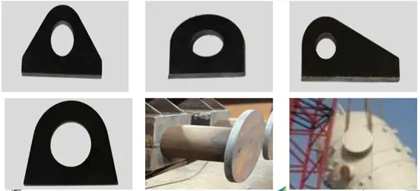
Lifting lugs can be of various shapes as shown in Fig. 2. The shapes are decided by manufacturers.
Lifting Lug Arrangements for Horizontal Vessels
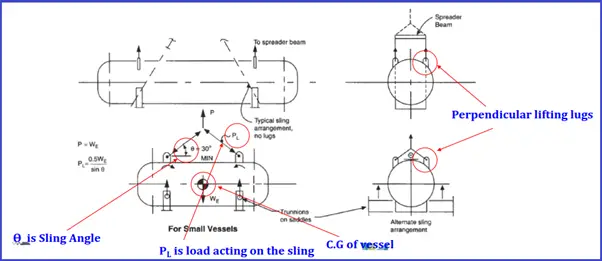
Fig. 3 shows widely used industrial lifting arrangements during construction for horizontal vessels.
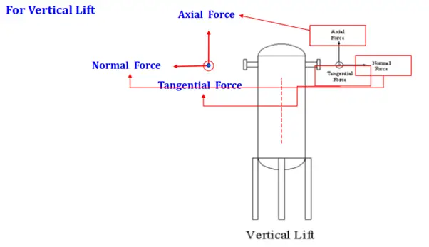
Lifting Arrangements for Leg-Supported Vessels
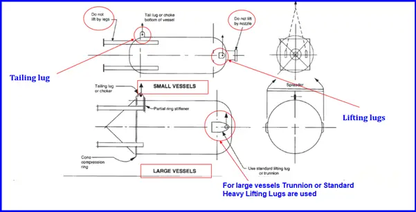
Fig. 4 shows typical lifting arrangements popularly used for vertical vessels in industries.
Forces in Lifting Lug Design
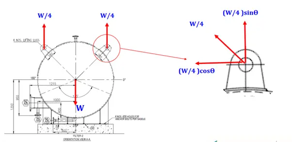
Horizontal to vertical lifting Forces:
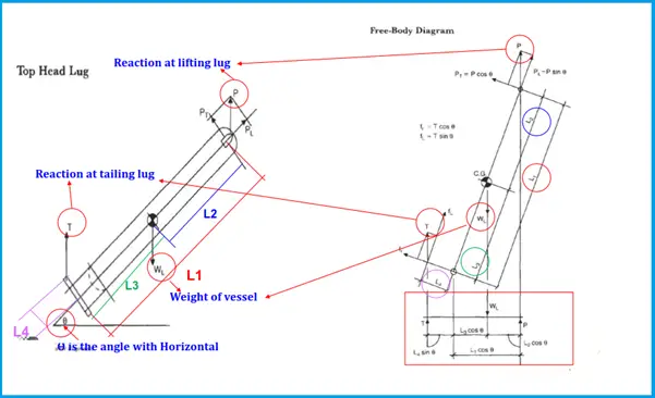
Horizontal to vertical lifting Forces Calculations:
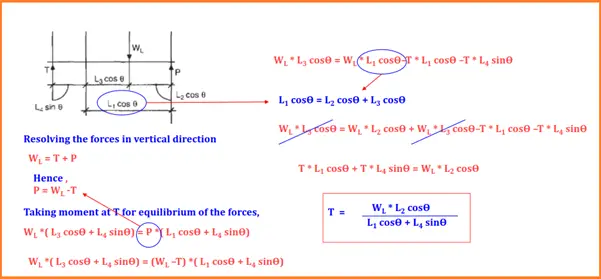
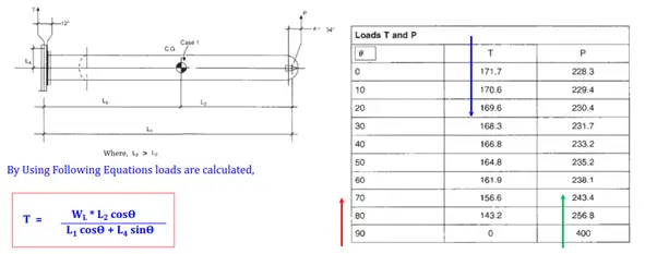
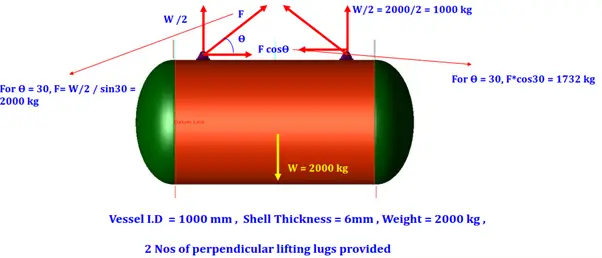
Horizontal to vertical lifting Forces Calculations with Sample Problem:
Lifting Lug design Standard
ASME BTH-1 “Design of Below-The-Hook Lifting Devices.” governs the design of lifting lugs for industries. For producing a safe reliable design, This is the most widely used lifting lug design standard. However, As such standards do not clearly address the local stress calculation steps, Finite Element Analysis is performed using various software like Ansys, PV-elite, etc.
Lifting Lug Design
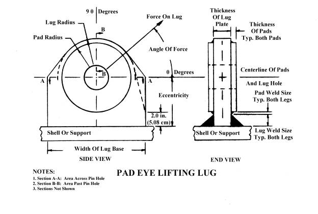
Lifting lug design is very critical and hence mostly done using FEA software. The basic design of a lifting lug consists of the following four parts;
- the design of the lug plate,
- verifying the weld used to connect it to a shell or structure,
- checking the bearing stress at the pin-hole and
- confirming the end area of the lug.
The following image shows the parts of a Pad-Efe Lifting Lug.
In the following section, we will see the design methodology followed for lifting lug design using PV-Elite software.
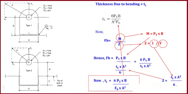
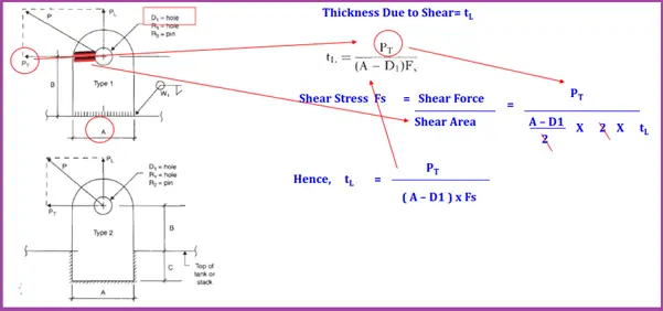
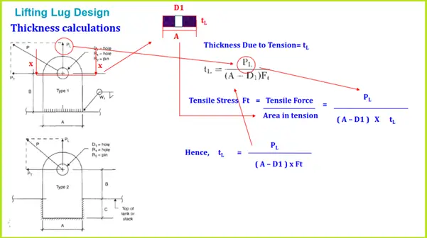
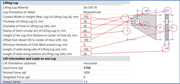
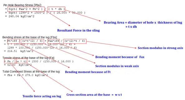
Lifting Lug design Thickness calculations:
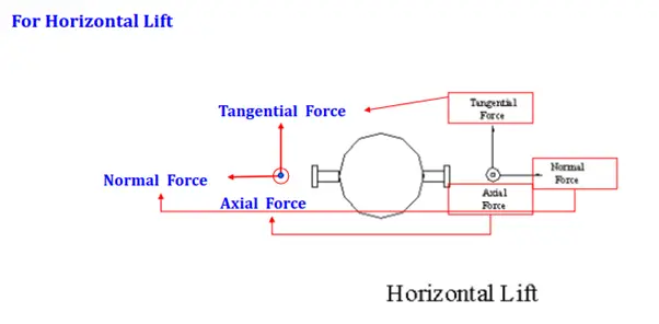
PV Elite Forces and sign Conventions:
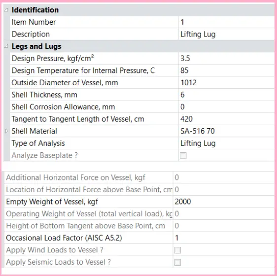
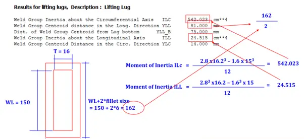
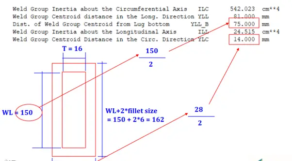
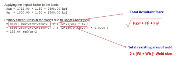
PV Elite Lifting Lug Sample Example
Factors Affecting Lifting Lug Design
Designing lifting lugs for process equipment and components requires careful consideration of a range of factors to ensure safe and efficient lifting operations. Some of the factors that can affect the design of lifting lugs include:
- Load capacity: The lifting lugs must be designed to safely support the weight of the equipment or component being lifted, as well as any additional weight from rigging, slings, or lifting accessories.
- Load distribution: The lifting lugs must be designed to evenly distribute the lifting load across the equipment or component to prevent damage or distortion during lifting.
- Center of gravity: The lifting lugs must be positioned at the appropriate location to ensure that the equipment or component is lifted in a stable and balanced manner.
- Equipment design: The lifting lugs must be designed to accommodate the specific shape and size of the equipment or component being lifted, as well as any protrusions or obstructions that may affect the lifting operation.
- Rigging and lifting accessories: The lifting lugs must be designed to accommodate the type and size of rigging and lifting accessories being used, such as slings, shackles, and spreader bars.
- Environmental factors: The lifting lugs must be designed to withstand the environmental conditions of the lifting operation, such as temperature, moisture, and corrosive substances.
- Standards and regulations: The lifting lugs must be designed to meet applicable industry standards and regulations, such as ASME B30.20, which outlines the design requirements for below-the-hook lifting devices.
Overall, the design of lifting lugs for process equipment and components requires careful consideration of a range of factors to ensure safe and efficient lifting operations. It’s important to work with experienced engineers and rigging specialists to select the appropriate lifting lug and to ensure that it is properly designed, load rated, and installed.
This presentation is prepared by Mr. Deepak Sethia who is working in ImageGrafix Software FZCO, the Hexagon CAS Global Network Partner in the Middle East and Egypt. He has extensive experience in using Caesar II and PV Elite software and troubleshooting.
Dear Sir,
would you like to share basic design calculation of the lifting lugs shown in figure number-4 (Different types of Lifting Arrangements:) in your blog page.
your prompt reply is highly appreciable.
Thanks & Best Regards,
Dinesh Patel
dp220209@gmail.com
Very Nice information and useful
this is very handy information regarding the topic. keep it up.
Hi Sir,
please send me a excel sheet for design calculations if possible. My mail is chatrapathikrishnaji@gmail.com
https://whatispiping.com/lifting-lug-design-using-pv-elite/
Thanks for the info! very much helpful
could you pls share some example pictures for “liftig lug single plate type” and “lifting lug double plate type” ?
Do the lifting lugs have spare parts to consider in the inventory system? or to be entirely considered as one part?
Do you have a fixed lifting lug xcel spreadsheet that calculates the stresses? I would be interested?
a very informative web and explaining the base but still i am looking forward to you to explain the reference standards for Trunnion Lug used in most of the oilfield equipment skid.