
A Gate valve is a linear-motion manual valve that has a vertical rectangular or circular disc that slides across an opening to stop the flow that acts as a “gate”. Generally used for isolation purposes fully open or closed, Gate valves are not suitable for throttling service because the high-velocity flow will cause a partially open disk to vibrate and chatter and will hasten the erosion of the disc and seating surfaces.
Functions of Gate Valve
The open/close flow is achieved by moving the gate of the gate valve into or out of the fluid-flow stream. The flow of the fluid through the valve can be in either direction. Gate Valve is commonly used in refineries and petrochemical plants where pressure is low, and less used in upstream facilities due to high operating pressure, long on/off times (requiring many turns of the handwheel to open it or to close it), and severe environmental conditions.
A full port gate valve provides a full line size (equal to pipe dimensions) thus resulting in a minimum-flow pressure drop, On the other hand, A Reduced port gate valve smaller than the line size (Flow area less than the pipe) causes a slightly high-pressure drop than a full port.
Gate Valve Parts
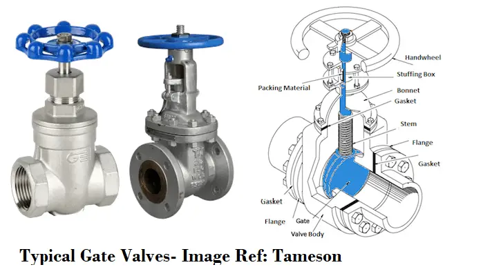
Refer to the below-attached figure (Fig. 1) which shows the main components of a gate valve.
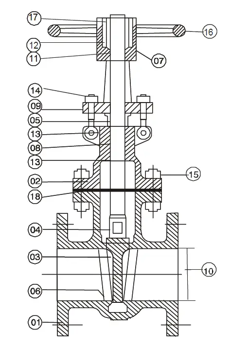
The items in Fig. 1 as per the corresponding numbers are given below:
- Body
- Bonnet
- Wedge
- Stem
- Gland
- Seat ring
- Yoke
- Packing
- Gland Flange
- Valve port
- Yoke Bush
- Lantern
- Back Seat Bushing
- Gland eyebolts & nuts
- Bonnet bolts & nuts
- Hand Wheel
- Hand Wheel nut
- Bonnet Gasket
There are three main parts in a Gate valve: body, bonnet, and trim.
- The valve body is connected to piping or equipment by means of flanged, welded, or screwed connections.
- The bonnet contains the moving parts which are connected to the body with bolts.
- The valve internal parts (removable and replaceable) that come in direct contact with the fluid are termed Valve trim which consists of the stem, the gate, the disc or wedge, and the seat rings.
Types of Gate Valves/ Gate Valve Types
Gate valves are divided into a number of classes, depending on their disc and type of stems. Gate Valves are classified by:
I. Gate Valve types as per Type of Closing Element:
1. Parallel disk Gate Valve:
Parallel disk gate valves consist of two discs that are forced apart against parallel seats by a spring at the point of the closure. The most famous type is the knife gate valve which has a flat gate between two parallel seats (an upstream and a downstream seat) to achieve the required shut-off. The application of a parallel gate valve is limited to low pressures and low-pressure drops.
2. Solid-Wedge Gate Valve:
The solid, or single wedge gate valve is the most widely used and the lowest cost used in the process industry for oil, gas, and air services. The purpose of the wedge shape is to introduce a high supplementary seating load. Solid-Wedge Gate Valve can be installed in any position, suitable for almost all fluids and practical for turbulent flow services.
In some situations, the valve cannot be reopened until the system temperature reheats the valve; this phenomenon is known as “Thermal blinding”. Wedge gate valves can be further described as inside screw or outside screw patterns. Solid wedge gate valves in the waterworks industry are popular as Sluice valves.
3. Flexible Wedge Gate Valve
A flexible wedge gate valve employs a flexible wedge that is a one-piece disk with a cut around the perimeter (the cut varies in size, shape, and depth). Thermal expansion and contraction entail no problems in such kinds of gate valves as the disk is able to compensate for this and remains easy to open. Flexible wedge gate valves are widely used in steam systems to prevent thermal blinding.
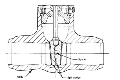
4. Split Wedge Gate Valve
Split wedges of this type of gate valve are made in two separate halves. This allows the wedge angle between their outer faces to fit the seat (self-adjusting and self-aligning to both seating surfaces).
5. Double-disc Valves
In these types of valves, the gate is in the form of two discs that are forced apart against parallel seats by a spring. this provides tight sealing without relying on fluid pressure, making this type of valve particularly suitable for steam duties as well as handling gases and light oils.
6. Bellows Seal Gate Valves
Bellows seal gate valves are designed to minimize exposure to harmful substances through valve-stem leakage. The bellow is a metallic device capable of sealing between the valve stem and the bonnet to prevent the escape of the system fluid to the atmosphere. The bellows take the form of convolutions that can move linearly. During operation, the bellows eliminate the leak path to the atmosphere.
II. Gate Valve types as per Type of Stem:
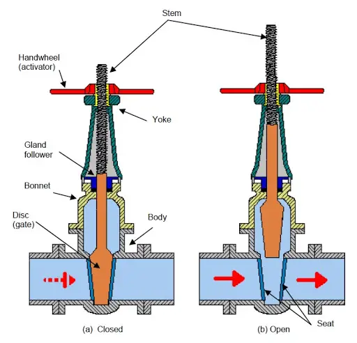
1. Rising Stem Gate Valve with Outside Screw
This type of gate valve is also known as OS & Y type (Outside steam and York). The stem rises while opening and lower while closing the valve offering an indication of the gate valve position. The stem threads never contact the flow medium (not subject to corrosion/erosion).
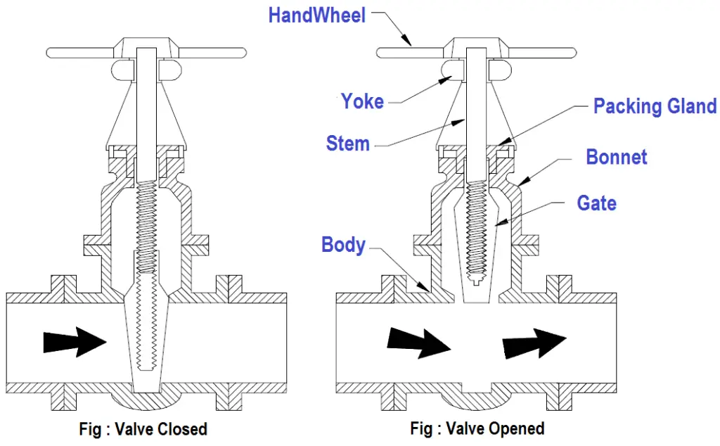
2. Non-Rising Stem Gate Valve
Also known as the Insider screw Valve, The stem of the non-rising stem gate valve is threaded into the gate. The hand wheel and stem move together and there is no rising or lowering of the stem. The stem is in contact with the flow medium.
Working of Gate Valves
The working of a gate valve is quite simple. When the gate of the valve is lifted from the flow path, the valve opens and when the gate again returns to its position, the gate valve closes. This gate movement is achieved by manually turning the hand wheel. The hand wheel rotates the valve stem and the internal threaded mechanism provides a vertical movement of the gate. As the hand wheel is turned more than one full cycle to fully open or fully close the gate valve, they are also known as multi-turn valves. Electrically actuated gate valves are available but not cost-effective.
Actuation of Gate Valves
Manual actuation of gate valves is invariably by screw and handwheel. The screw mechanism may be exposed or protected and the screw rising or non-rising. A variety of materials for the working parts is offered by some manufacturers.
Power actuators are very often fitted when the gate valves are difficult to access and are operated frequently. automation and semi-automation control schemes make extensive use of actuators.
Advantages of Gate valve
Gate valves are adequate for high-pressure and temperature applications. The main advantages of gate valves are:
- Provide very good shutoff characteristics.
- Low Pressure-Drop; very low frictional loss.
- the maintenance requirement is less.
- can be used as a Bi-directional valve
- low cost
- available in various sizes.
Disadvantages of Gate valve
- Cannot be used for throttling service.
- Slow disc movement in operation, it takes time to fully open or fully close.
- Lapping and grinding repairs are difficult to accomplish.
- May create noise and vibration when partially open.
- Prone to Seat and Disk wear.
Gate Valve Materials
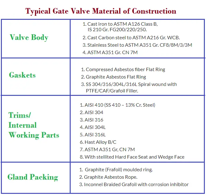
Various types of materials are used for gate valve construction. Typical common materials used are cast carbon steel, cast iron, ductile iron, gunmetal, bronze, alloy steel, stainless steel, and forged steel. Brass and PVC gate valves are used for plumbing services. The material selection for gate valves primarily depends on fluid service and its design temperature. The following table provides a typical example of common materials used in Gate valve construction.
Applicable codes and standards for gate valve design
The following codes and standards govern the design specification of gate valves:
- Valve Design: API 600/ API 602/ BS5352/ API 603/ API6D/ IS780 /BS 1414 / BS 14846
- Valve Pressure Testing: API 598
- Valve Pressure Temperature Rating: API B16.34
- Face-to-Face Dimensions: ANSI B16.10
- Flange Drilling: ANSI B16.5 / ASME B 16.47/ BS 10 Table / DIN /IS /JIS Standards
- Butt/ Socket Welded End: ANSI B16.25 and B16.11
- Screwed End: ANSI B 1.20.1 (BSP/NPT)
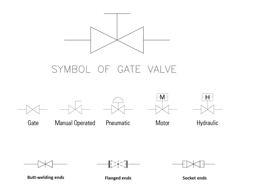
Gate Valve Symbols
The gate valve symbols used in the different organization varies a little bit. Normally any one of the following three types of gate valve symbols given in Fig. 9 is used as a gate valve symbol.
Gate valve vs Ball Valve
Both the gate valve and Ball valve are widely used for isolation services in the oil and gas industries. However, there are a few differences between the gate valve and the ball valve. Some of such differences are listed below in a tabular format for reference:
| Parameter | Gate Valve | Ball valve |
| Working Principle | Gate valves control the valve using its gate. When lifted up, allows full flow, and when down, no flow. | Ball valves feature a stem and a ball with an opening inside. When the opening is lined up with the pipe by turning the control lever fluid can pass, otherwise, the valve is off. |
| Cost | Gate valves are Relatively cheaper | Ball valves are comparatively Costlier. |
| Turning of lever or hand-wheel | Gate valves feature a Multi-Turn mechanism. | Ball valves are Quarter-turn valves. |
| Weight | The weight of the Gate valve is normally less than the ball valve for the same size and rating. | Ball Valve weights are comparatively more than gate valves. |
| Shut off capabilities | The shut-off capabilities of gate valves are not at par with ball valves. | Comparatively better than gate valves; more reliable. |
| Surge Probability | As the operation of a gate valve is slow, less probability of water hammer. | Ball valves are more prone to water hammer or surge creation. |
| Vibration probability | Partially open gate valves cause vibration or noise | The possibility of noise production is less in ball valves. |
| Operating Space requirement | The operating space requirement for gate valves is usually less. | More space is required to operate a ball valve. |
| Visual Clue for on/off position | No clue from the outside, it’s simply guessing. | Easy to understand if the ball valve is in the open or closed position. |
Few more related articles for you.
Selection of Valves: A Few Guidelines
Details about Control Valves
Ball Valve Design Features: A Detailed Literature
A brief article on Valve Inspection & Testing
Control Valve Sizing Procedure: Valve Flow Terminologies, Control Valve Characteristics, Cavitation and Flashing
sir, you have explained about the gate valve in good detail and also explained the difference between the gate valve and the bol valve.
thank you sir????????
I like the way you have explained this will help me in an exams thanks you
you are welcome sir
Hi Said,
Very informative. It would be useful if possible to compare Gate vs Globe vs Piston vs Ball valve in a single table.
Thanks,
Darshan Trivedi
Can you please clarify whether gate valves can be used as sectionlising valves in cross country gas pipelines?
Hi Sir,
Well explained however can elaborate between Gate Valve Class A & Class B variance?
Thank you
An important issue that is not addressed by anyone I can find: when a gate valve is operated in a steam system with condensate accumulation possible : when initially opened, fluid can go under the wedge AND over it thru the bonnet. This is important because if steam is being admitted to sub cooled condensate on the other side of the valve, the steam going under the wedge will not cause a Condensation Induced Waterhammer, but, I think, the steam going over the wedge thru the bonnet and into the top of the condensate filled pipe will hammer.
It’s nice that you talked about how a gate valve is a linear-motion manual valve that has a vertical rectangular or circular disc that slides across an opening to stop the flow that acts as a gate. I was reading a pretty interesting magazine article earlier and I learned about how gate valves work. Additionally, it seems gate valve bonnet replacements are easily available now too.