
Major valve parts include two types of functions, namely pressure-retaining, which includes a valve body, bonnet or cover, Cover bolting, Disc, and the other major non-pressure-retaining parts of a valve, like a valve seat(s), stem, yoke, packing, gland bolting, bushings, handwheels, valve actuators, etc.
Within all these removable and replaceable internal parts of the valve, some will be directly in contact with the fluid flowing through it. These internal parts of the valve are collectively called valve trim. Valve trims play a critical role in the functioning of fluid control systems across various industries, from oil and gas to water treatment and HVAC. In this article, we will explore what valve trims are, their types, applications, and the factors to consider when selecting them.
What Are Valve Trims?
The term “valve trim” refers to the internal components of a valve that control the flow of fluid through it. This includes elements such as the stem, disc (or plug), seat, and any additional components that contribute to the valve’s operation. While the valve body provides the outer structure and connects the valve to the piping system, the trim is responsible for regulating flow, preventing backflow, and sealing against leakage.
These operative parts control the flow of liquid and gas through a valve. They are the parts exposed mostly to the process elements, and so are very vulnerable to wear over time. The stem, ball, and seat are the three basic items of the high-pressure control valve trim. So as the valves change, trim components also may vary except the disc, valve seat, and stem. This will be common for all the valves. As the trim parts, the disc movements, and the flow control are possible.
Some of the other valve trim components, as the valve specific, include,
- Back seat
- Glands
- Spacers
- Guides
- Bushings
- Retaining pins
- Internal springs
Valve Trims according to the Type of Valves
Refer to Table 1 which shows the valve trim elements for different types of valves.
| Type of Valves | Valve Trims |
| Angle Valves | Stem, Seat, Disc, Disc nut, back-seat bushing |
| Gate Valves | Stem, Seat, Wedge, back-seat bushing |
| Globe Valves | Stem, Disc, Seat, Disc nut, back-seat bushing |
| Disc Valves | Disc, Disc nut, back-seat bushing |
| Lift-type check valves | Seat ring, Disc, Disc guide |
| Swing-type check valves | Seat ring, Disc, Disc nut, Disc nut pin, Disc holder, Disc holder pin, side plug, carrier pin |
Importance of Valve Trim Design
The trim plays an important role in the characteristics of the valve. It determines the flow rate and the isolation of the valves. The shapes of the valve trim determine the flow characteristics of the valve. A valve trim’s characteristic is related to the percentage of flow and the valve stem travel between 0% and 100%.
Trim materials are sometimes the same material as the valve body or bonnet, and sometimes they differ. As per the different properties, required for the components to withstand particular forces and conditions. so that they are constructed of assorted materials. When suitable trim materials are selected, the flow-medium properties like chemical composition of the fluid, pressure, temperature, flow rate, velocity, and viscosity of the fluids are considered.
Valve trim components and valve characteristics
1. DISC
The disc is a part of the valve which allows, throttles, or stops flow depending on its position it is a pressure-retaining part of the valve. Types of discs present on the valve define the name of the valve. over plug or ball valve, the disc is called a plug or ball. A disc will be seated against the stationary valve seat or seats when the valve is in the closed position, during the closed position the disc performs a pressure-retaining function whereas, during the valve open position, the disc doesn’t perform the pressure-retaining function. It can be moved away from valve seats by the motion of the valve stem, except in the check and safety relief valves the disc is moved away from its seats by fluid flow and pressure. A valve disc is usually cast, forged, or fabricated.
2. SEAT
A valve seat is one of the non-pressure retaining parts of the valve. Valves will be having maybe one or more than one seat, as in the cases of globe or swing check valve, there will be one seat forming a seal with the disc to stop the flow. Whereas for the gate valve, there will be two seating surfaces that will come in contact with the seats. Likewise, ball and plug valves, depending on the number of ports will have several seats. Valve seats can be integral, renewable, or replaceable rings. Small valves are provided with screwed-in, swaged-in, or welded valve seats, and in big valves, they may have any of the seats used in small valves and they will have integrally cast or forged seats along the valve body.
The leakage rates within the valves are directly proportional to the effectiveness of the seal. Between the disc and its seat. The acceptable leakage rates are specified by the valve standards MSS SP61, API 598, and ASME B16.34.
3. BACK SEAT
The back seat is another non-pressure retaining part of the valve. The back seat is made up of a shoulder of the stem. When the stem is in a fully open position it forms a seal. Thus, preventing the leakage from the valve shell, to the packaging chamber and the environment.
4. STEM
The stem connects the actuator, valve handwheel, and the disc, plug, or ball. Required for the opening and closing of the valve motion. Thus, the motion of the stem opening and closing the valve took place. In a gate or globe valve, linear motion of the disc is needed to open or close the valve. Whereas in the plug, ball, and butterfly valve, the valve disc is rotated to open or close the valve. Stop check valves, and check valves do not have any stem.
5. BONET BOLT
Bolting includes bolts, nuts, and washers. They hold the bonnet and the body creating a tight pressurized seal between them. Bolting should be selected under the application code and standards as per the materials applied.
6. GLAND EYEBOLT
It connects the gland flange and the bonnet and tightens the bolts.
7. YOKE
Yoke is also called yoke arms. The actual mechanism of the valve is connected with a yoke to the valve body or bonnet. Over many valves, The yoke and the bonnet are designed as a one-piece construction. The top side of the yoke consists of the yoke nut and yoke bushing. To withstand forces, moments, and torque developed by the actuators, the Yoke is made hard enough.
8. YOKE BUSHINGS
It is the part where the internally threaded nut is held at the top of the yoke where the valve stems passes through. In some valves, like the gate and diaphragm. the nut is turned and the stem moves up and down which depends upon the direction of turning. Over some valves, the yoke nut is held fixed permanently and the stem is rotated through it. For the minimal effort of actuating, the yoke bushings are made up of softer material than the stem. anti-freeze yoke sleeve bearings are provided on the valves that require much effort to open or close. This will minimize the friction between the hardened stem and the yoke bushing.
9. GLAND FLANGE
Used to provide support for the gland bush to keep the gland packing under tension.
10. STEM PACKING
Depending upon the application stem packing performs applications like
- Preventing leakage of flow medium to the environment.
- Preventing outside air from entering the valve during vacuum applications.
It is contained in a stuffing box. Packing rings get compressed by tightening the packing nuts or packing gland bolts. Compression over here must be sufficient to make a good seal. Stem packing is made of graphite or PTFE as per the requirements.
Types of Control Valve Trims
The valve trim shape determines the flow of characteristics of the valve in the control valve. There are three primary types of control valve trims.
1. Snap Trim (also referred to as Quick-Opening trim)
it opens quickly and is used for isolation services. Which includes the primary operations like a liquid dump, pressure relief, and metering.
2. Nominal Trim(also called Linear trim)
It is used for throttling liquids, liquid level control, and in applications where a water hammer is an issue.
3. Equal Percentage Trim
They are used to control the pressure or flow of gases and vapors in throttling applications.
Trim selection against Corrosion & Erosion
Based on the service conditions like the temperature, pressure, type of fluids, chemical composition, flow velocity, pressure drop, maintenance need, etc. valve trims are selected. The sustainability of the material, to resist corrosion can be determined by corrosion resistance tables and selecting accordingly from them.
And erosion is caused due to high-velocity liquids with abrasive particles harder than trim material.
Metallic Valve Trim Material
AISI type 316 stainless steel has been the most common trim material. The metallic trim is good for all-around choice in general service for about -195 Deg C to +400 Deg C and moderately corrosive fluids. Alloys of steel, titanium, Cobalt-Chromium alloys and Nickel-Boron alloys are some of them used.
Non-metallic Trim Material
Operating temperature is the most important factor in selecting non-metallic trim material. Poly tetra fluoro ethylene (PTFE), Teflon, etc.
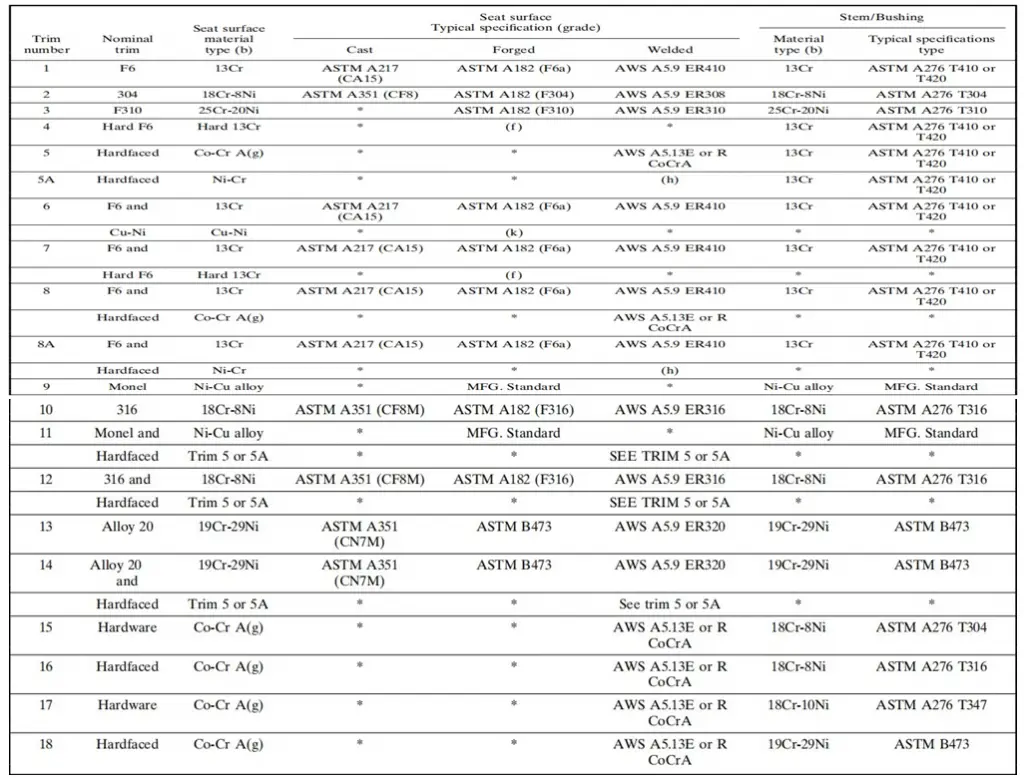
Valve Trim Chart
For standardizing trim materials API has assigned a unique number to each set of valve trim materials. Trim numbers or combination numbers consisting of materials like disks, stem, back seats, and sleeves are grouped and assigned to one number.
- API 600 & 602 gives the list of Trim materials that can be used in the valve.
- ASTM A410 (13Cr), ASTM A316, Alloy 20 (19Cr-29Ni), and Monel (Cu-Ni Alloy) are commonly used trim grades.
Refer to the figure below to find a typical Valve trim chart as provided by API 600 and API 602. The chart is defined by Trim numbers.
Valve trims are integral to the functionality and efficiency of fluid control systems. By understanding the components, types, and considerations involved in selecting valve trims, engineers and operators can make informed decisions that enhance system performance and reliability. Whether in oil and gas, water treatment, or HVAC applications, the right valve trim can lead to significant operational improvements and cost savings.
Want to get n in-depth knowledge about Valves, their principles, operations, and design then click here to learn online.
which valves is better as per trim , trim 1 or trim 5&8
Please revert