In piping instrumentation, LC and LG refer to two different types of level measurement devices:
- LC: LC stands for “level controller” or “level control switch”. This is a device that is used to monitor the level of a liquid in a tank or vessel and control the filling or draining of the tank based on the desired level. The LC typically sends a signal to a control system or actuator to open or close a valve based on the level of the liquid.
- LG: LG stands for “level gauge” or “level indicator”. This is a device that is used to visually or electronically display the level of a liquid in a tank or vessel. The LG typically consists of a glass or plastic tube that is mounted on the side of the tank and filled with liquid. As the level of the liquid changes, the level in the tube changes, allowing the operator to easily monitor the level of the liquid.
Both LC and LG devices are commonly used in industrial and process piping systems to monitor and control the level of liquids in tanks and vessels. By providing accurate and reliable level measurement, these devices help to ensure the safe and efficient operation of the system.
This article shall be applied to process engineers’ preparation of basic requirements to enable the piping engineers to finalize LC-LG Arrangements. LC-LG arrangements should be prepared through engineers in process engineering, control engineering, piping engineering, and the mechanical engineering department’s close collaboration. Total coordination should be executed by the piping engineer.
Work Step of LC-LG Arrangement
The piping Engineer should prepare a datasheet based on the skeleton drawings. The following items shall be filled.:
- ① Vessel Item Number
- ② Service
- ③ Instrument Tag Number
- ④ P&ID Numbers
- ⑤ Dimensions of Equipment
(Prepare a sketch of the Equipment outline and liquid levels) Then, the datasheet shall be sent to the process department.
Process condition shall be filled in, and visible range/control range shall be indicated by Process Engineer
- ① Design Pressure & Temperature
- ② Operating Pressure & Temperature
- ③ Fluid Name
- ④ Operating Specific Gravity
- ⑤ Visible range
- ⑥ Control range, if required
Then, the data sheet shall be sent to the control engineering department.
The instrumentation Engineer will select the LC type according to the detailed engineering design data of instrumentation, and the following data shall be filled in.
- ① Quantity of level instrument
- ② Type of level instrument
- ③ Length (Center to center, Visible range)
- ④ Connection Size / Rating
- ⑤ Line Class
Then, the datasheet shall be sent to the piping department.
Now piping engineers will select LG type based on process condition, and the following data shall be filled in.
- ① Quantity of Level Gauge
- ② Type of Level Gauge
Decide the nozzle height and valve assembly. Such information shall be indicated on the datasheet.
Then, the data sheet shall be distributed to the disciplines concerned.
- The mechanical Engineer will check interference between the nozzle welding line and the equipment welding line. If any, nozzle height shall be adjusted by the piping engineer.
- Finally, the LC-LG arrangement shall be followed to P&ID by Control/Instrumentation Department
LC-LG Design Criteria
Fluid conditions:
- The fluid name shall be specified.
- Polymerization, fouling, slurry, and other data required for the selection of LCs and LGs which are not indicated on P&IDs shall be entered in the process data sheets.
- In the case of multi-phase fluid, the specific gravity of the individual fluid shall be entered.
Level Control (LC)
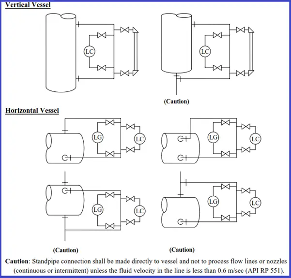
The typical arrangements of level instruments are indicated below in Figure 1.
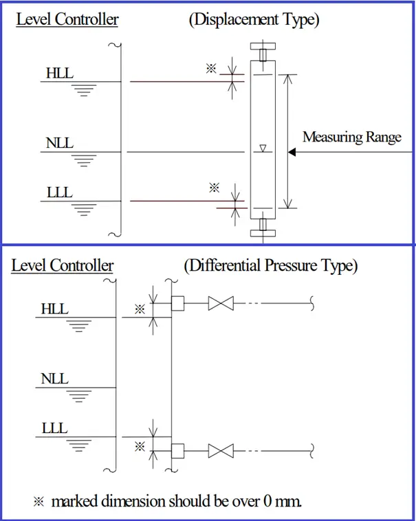
The external covered displacement type or deferential pressure type level instrument should be selected on the following basis:
- Visible length over 1200 mm(4FT) : Deferential Pressure Type
- Differential pressure of differential pressure type level instrument should be recommended over 500 mm H2O. (Measuring range ≧ 500/Sp Gr)
- The diaphragm seal type is recommended for corrosive fluid.
- The external displacement type shall not be used for flashing services or averted external radiation services.
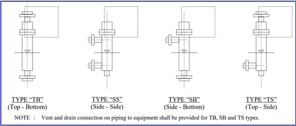
If displacement types are to be used, their installation types shall be entered according to the fluid properties and the client’s instructions, etc. Normally, side-side(“SS”) LCs shall be used.
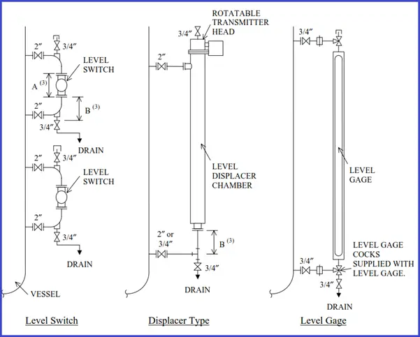
Connection Type of Displacement Level Instruments
Level Switch (LS)
- LS and LC should be installed on the same standpipe. However, LS and LC shall be installed separately for cloggy services.
- The type of LS should basically be external ball float or displacement type.
Level Gauge (LG)
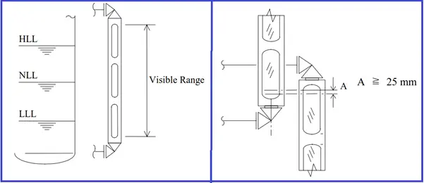
- The visible range of LG shall cover the control range of LC.
- In the following services, through vision type gage glass should be used.
- Liquid-liquid interface
- Fluid under 20° API
- Crude or residue oil
- Fluid includes gum or sediments
- If the measuring range is large for covering with one LG, two or more LG shall be used. However, the visible range of each LG shall be overlaid as follows:
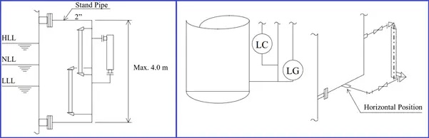
- If the plural numbers of LGs are needed, the standpipe can be used. The standard size of the standpipe connection should be 2 inches and the maximum length of the standpipe shall be 4 m. If the standpipe length is over 4 m, the standpipe size should be increased.
- In the case of standpipe connection and Low Liquid Level (LLL) is very close to the vessel welding line,LG can be connected at the same level of the horizontal portion of standpipe.
- Connections to vessel -Level instrument connections shall be made directly to vessels and not to process flow lines or nozzles (continuous or intermittent) unless the fluid velocity in the line is less than 0.6 m/sec (API Recommended Practice 551). Connections and interconnecting piping should be installed so that no pockets or traps can occur.
Level Instruments Mounted Direct to Vessel
The typical arrangements of the level instruments to be mounted directly to the vessel are as follows:
Level Instruments on Standpipe: Typical Arrangement-
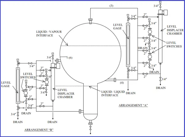
Recommended LC LG Arrangement
The typical LC and LG arrangements are shown in the figures below: