
The purpose of the article is to define what we mean by chemical process control & the objective of controlling a chemical process.
What is Process Control?
Basically, process control means maintaining the desired condition in a chemical system by adjusting the selected process variable. It deals with science & technology. The process variables can be temperature (T), Pressure (P), Level (L), flow rate (F), etc.
For an appropriate design & implementation of a control system, the controller must be based on a complete understanding of the process dynamics. Process control is a control of an output variable by sensing the amplitude of the output variable from the process comparing it to the setpoint value and causing an error signal fed back to the controller to take control action through the final control element (e.g. control valve).
Why Process Control?
The main objective of process control includes many advantages including,
- Enhanced process safety
- Meeting environmental constraints& compliances
- Satisfying product quality &specifications
- Protection of Equipment & Environment
- Enhancement of profitability
- Smooth Operation
What is a Control System?
A control system is used to retain process conditions at their desired level by manipulating certain process variables (PV) to adjust the target variables. A common example is the fuel gas flow to the heater (the manipulated variable). The controller compares the measurement signal of the controlled variable to the setpoint (the desired value of the controlled variable). The difference between the two values is called the error.
What is an Error?
Error is defined as follows, Error= (Setpoint value)– (Measurement signal of controlled variable). Depending upon the magnitude and sign of the error, the controller takes appropriate action by sending a signal to the final control element, which provides an input to the process to return the controlled variable to the set point.
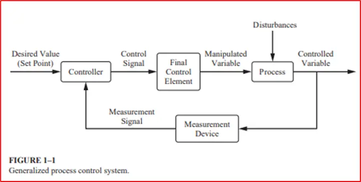
What is a Block diagram?
A block diagram is a pictorial representation that shows the flow of information around the control system and the function of each part of the process.
What is a Closed-loop?
A control loop is called a closed loop when the measured value of the controlled variable is fed back to the controller.
What is a Controlled variable?
The controlled variable is the variable of the process that we want to control at a particular value.
What is a Controller?
The controller is the heart of the control systems that can be called a decision-maker. Basically, it is a hardware element with a built-in capacity for performing the only task requiring some form of intelligence. Some examples are pneumatic controllers, electronic controllers, etc. It generates a signal to the process depending on the magnitude of the error signal. A proportional controller (P) creates a signal that is proportional to the error.
What is Disturbance Rejection?
One goal of a control system is to enable the system to “reject” the effect of disturbance changes and maintain the controlled variable at the set point.
What are Disturbances?
Disturbance can be any process variable that can cause the controlled variable to fluctuate. Generally, disturbances are those variables over which we have no control.
What is a Manipulated Variable?
Manipulated variables are those process variables that are adjusted so that the controlled variable can be brought back to the set point.
What is an offset?
The steady gap or error between the setpoint value (SP) and (PV) is called offset in process control.
What is an Open-Loop?
An open loop is just the opposite of a closed loop as the measured value of the controlled variable is not fed back to the controller.
What is a Set Point?
Setpoint the values at which we want to control the controlled variable. This value needs to be given manually to the controller.
What is a Sensor/Transmitter?
A sensor is a device that detects the process variables, such as temperature, pressure, flow rate, and level, and has the ability to give a measurable output that varies with respect to the change of the physical variable. The sensor gathers information about the status of the process variables (PV).
The transmitter converts the measured electrical or mechanical phenomenon to 3-15 PSIG pneumatic signals, a 4-20-mA electrical signal, or a 0-5 V DC voltage or digital signal that can be transmitted to the controller.
Some examples of sensors are thermocouples (for temperature measurements), differential Pressure cells (for liquid level measurements), gas/liquid chromatography (for Composition measurement), etc.
What are Signal Converters?
Signal converters in a feedback control system convert the pneumatic signal (3–15 PSIG) to an electronic signal (4–20 mA), or vice versa. This conversion is accomplished by certain hardware units called pneumatic-to-current (P/I) and current-to-pneumatic (I/P) converters. In addition to that, it is required to convert an analog signal to a digital signal by an (A/D) and a digital signal to an analog signal by a (D/A) converter. The use of an analog and/or digital filter is also quite common to get rid of undesirable processes and transducer noise. Due to the fast response of a signal converter, no dynamics are associated with these units.
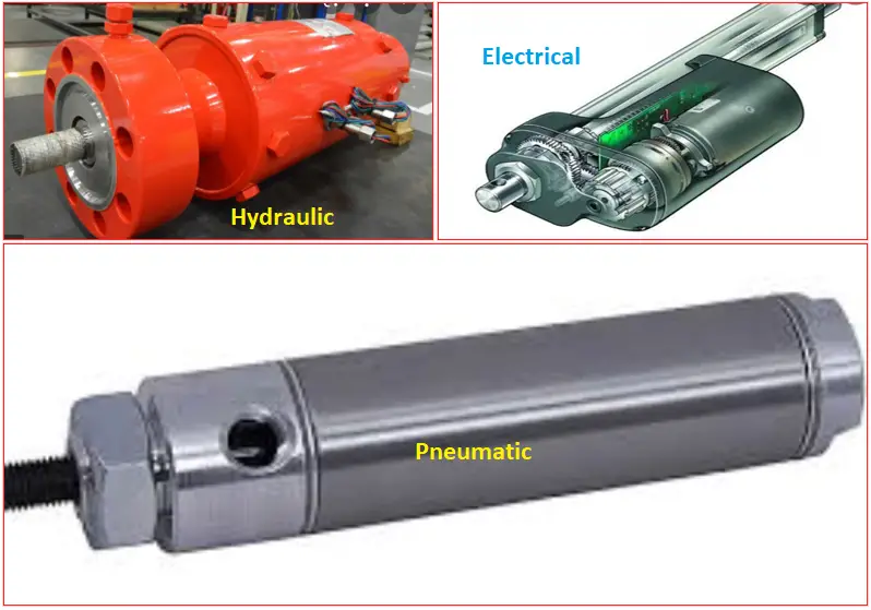
What is an Actuator?
An actuator is a mechanical device that generates a motion through the conversion of energy and signals generated by the controller. The motion generated by the actuator can be rotary or linear. Linear actuators produce linear motion. So it is very apparent that linear actuators can move forward or backward direction. The flow control valve is a typical example of an actuator that controls the rate of flow of a fluid in proportion to the amplitude of an electrical signal generated by the controller. There are different types of actuators used in industry that could be electrical, pneumatic, or hydraulic. The selection of actuator type will most likely depend on the application and -specific requirements.
| Type | Advantage | Disadvantage |
| Hydraulic | Can handle loads of more than 10 kN. | It requires pumps, valves, tanks, hoses & regulators. |
| Pneumatic | Movement is very fast between two points. | It requires valves, tubes & compressors. |
| Electrical | Very simple, and causes low sound & energy savings. | Lower speed than compared to others, less suitable for heavy loads. |
What is the Final Control Element?
The final control element is none other than the actuator that throttles the manipulated variables based on the command signal it receives from the controller. In the chemical industry, the manipulated variable is often the flow rate of a process stream (e.g., the steam or cooling water flow rate for temperature control, the flow rate of gas or liquid, the solid flow rate of a catalyst using a slide valve or a screw conveyor, etc.). The most commonly used final control element for throttling a flow rate is a control valve. Some other final control elements are a variable speed pump, a silicon-controlled rectifier (SCR), and an immersion heater.
What is Feedback Control?
Feedback control is based on the measurement of the controlled variable (process variable, PV) by a proper sensing element and transmitting the measured signal to the controller. The desired value of the controlled variable that is put manually is also made available to the feedback controller as the setpoint (SP). The controller subtracts the measured controlled variable from its set point and calculates the error signal. The error signal triggers the control law and calculates corrective action and this action is implemented by the final control element.
The steps that are performed by the feedback control strategy are as below,
- Measurement of the desired process variable directly or indirectly by a sensor/transducer;
- Compare the measured variable with its set point & calculate corrective action (decision);
- Implement the corrective action, using a final control element such as the control valve.
What is the ON-OFF Controller?
The ON-OFF controller is the simplest type of feedback controller. Based on the position of the controlled variable relative to the setpoint it drives the manipulated variable from fully closed to fully open or vice versa. This means that the control element does not operate at any intermediate position between 0-100% ranges. In ON-OFF control when the process variable changes and deviates from a certain set point the output variable of the system is fully opened all of a sudden. The ON-OFF controller is also called a Bang-Bang controller or two-step controller.
In the below figure you can see the water level in the tank is regulated through ON-OFF installed on the water supply line. Most of the time ON-OFF valve is used as SDV (Shut down valve), and EIV (Emergency isolation valve) in a process.
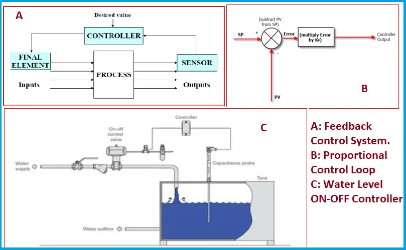
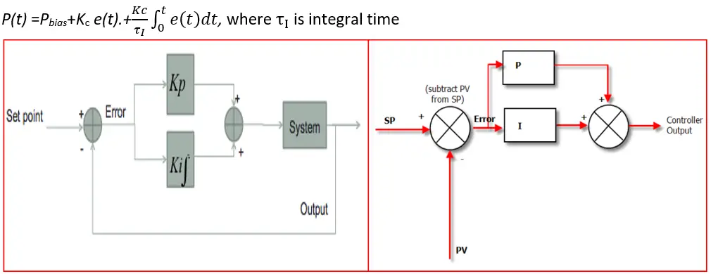
What is a Proportional Controller?
Proportional controllers’ output is proportional to the magnitude of the error signal. The proportionality constant, Kc, is referred to as the controller proportional gain, Pbias is the controller bias that is the output generated from the controller when the error signal becomes zero. In short, it is a linear type feedback controller through which the corrective action is implemented to the controlled variable that is proportional to the error.
P(t) =Pbias+Kc e(t), where P(t) is the controller output at time t.
What is Proportional Integral (PI) Controller?
This controller’s output is proportional to the magnitude and time integral or duration of the error signal. τ1 is referred to as the controller integral time or rest time. PI controller is a close control loop of a feedback system. It continuously detects an error signal (the difference between a measured process variable and the desired setpoint). P-controller acts as a multiplication factor to the magnitude of the error & generate output. I-controller keeps a certain value based on the difference between the reference (that we want as output) & the actual value of output. So, I- the controller is the summation of the error signal over some time that is generally moving to & fro from a setpoint.
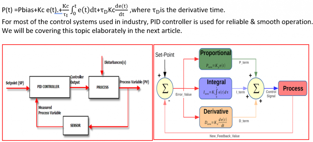
What is Proportional-Integral-Derivative (PID) Controller?
A PID controller is a widely used control system that is used in almost all industrial processes to regulate temperature, flow, pressure, speed, and other process variables. The PID stands for Proportional-Integral-Derivative which uses a control loop feedback system to control process variables (PV) and it is one of the most accurate and stable controllers. The output of the PID controller is proportional to the magnitude, duration (time integral), and time rate of change (derivative) of the error signal. τD is designated as the controller derivative time or rate time. Here the derivative action predicts the future as it predicts what is yet to happen by projecting the current rate of change into the future. The equation that calculates the control action of a PID controller is
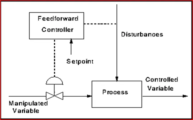
What is a Feed-Forward Control?
Feed-forward control is a control system that predicts the influences of the disturbances and manipulated input on the relevant process variables. This model responds in a pre-defined way without responding to how the load reacts. So it is not an error-based control system rather it depends on the mathematical model of the process. This control strategy can be highly effective and largely suppress the impact of disturbances. So in this control system, the disturbances are measured & corrective action is implemented before the disturbances have time to affect the system.
Feed-forward Vs Feedback Control
The main advantages of a Feedback control system are as follows,
- Corrective action is generated as soon as the controlled variable deviates from the desired set point, irrespective of the source and type of disturbance.
- Feedback control needs very little knowledge about the process to be regulated. In particular, no mathematical model of the process is required, although it can be very needful for designing the control system.
- The PID controller is both versatile and robust in nature. If the conditions of the process change, the controller usually produces satisfactory control.
At the same time, Feed-forward control has several disadvantages like,
- The value of the disturbance variables must be measured online. In many applications, this is not practically feasible.
- At least an approximate process model should be available to make effective feedforward control. Particularly, it is required to know the response of the controlled variable with respect to the changes of both the disturbance and manipulated variables. The quality of feedforward control solely depends on the accuracy of the process model.
- Ideal feedforward controllers that are theoretically able to achieve proper control of the system may not be physically realizable.
In practical application, feedback control is preferred over feedforward control.
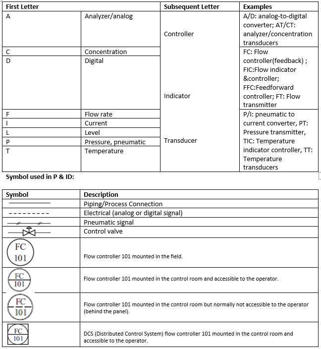
Example of the letters used in a P&ID
Online Video Courses On Process Control
Want to have more insights into the process control fundamentals? Then the following online video courses are a must for you: