In this article, We will learn the stress classifications as per ASME B31 and ASME BPVC codes in detail.
Stress Classification in ASME B31
For performing stress analysis while designing a system, the following three fundamental details are required
- Types of Load acting on the system
- Modes of failure due to the applied loads, (Basis for Stress classification)
- The allowable limit for the various modes of failure. (Basis for Allowable Stress)
Types of Loads in Piping
Various loads acting on the piping system can be broadly classified into two categories.
- Primary Load
- Secondary Load
The pipe will react differently for these loads. Hence, a different mode of failure and different allowable limits.
Primary Load:
According to ASME primary stress is defined as “A normal or shear stress developed by the imposed loading which is necessary to satisfy the laws of equilibrium of external and internal forces and moments”.
This includes Fluid pressure, Pipe weight, Insulation weight, cladding weight, refractory weight, externally applied forces like Slug, Surge, Reaction forces, and Fluid weight.
When a primary load is acting on a piping system, stresses will be induced in the system and these stresses are depending on the Geometric property of the pipe (Diameter, and Thickness). But, Displacement (Strain) is a function of Young’s modulus (E). Let us take an example situation shown below.
Primary Load example

A Bar of hollow circular cross-section with uniform thickness “t” is experiencing an axial pull of load “P”. From the elemental mechanics,
Stress, σ = P/A
Strain, ɛ = σ/E
Where,
A = Cross-sectional area
E = Young’s modulus
Since the Primary load should satisfy the equations of equilibrium, the applied load will be equal to loads at restraint in CAESAR II. i.e. Loads in the system = Sum of loads at restraint. An example is given below.
Weight report of the system:

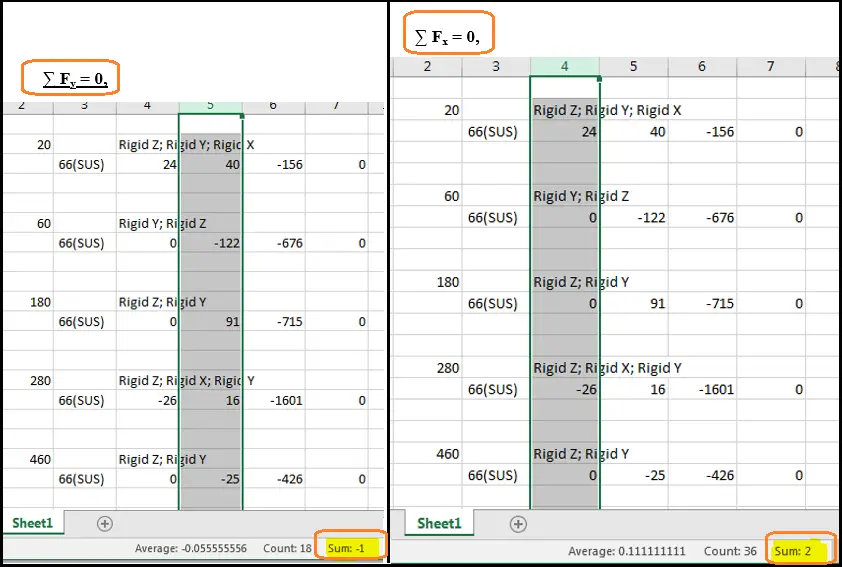
The below images show the sum of “Vertical Restraints” for the same system for the WNC case which is equal to the dead weight of the system shown above. (a slight error is due to rounded-up values)
Applying the Equation of equilibrium,
- ∑ Fx = 0,
- ∑ Fy = 0,
- ∑ Fz = Weight of the system,
- X, Y – Horizontal direction, Z-Vertical direction
∑ Fz = Weight of the system,
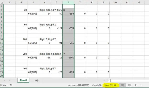
So total vertical force in Fig. 2 and Fig. 3 are almost equal.
The same is true for Fx and Fy forces as well which can be confirmed by Fig. 4.
Secondary load:
A hollow circular bar is fixed on one end and it is heated. Now, the Bar will expand and no loads will be generated in the fixed end as shown in Fig. 5A.
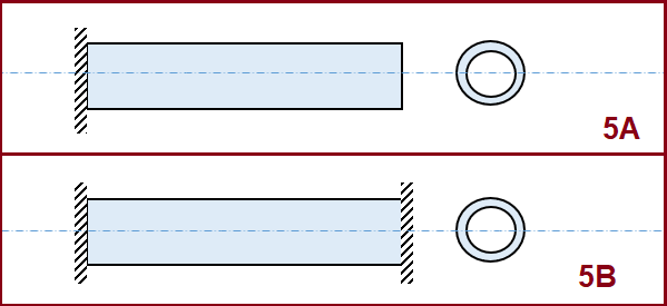
Now, the same bar is fixed on both ends (Fig. 5B) and the bar is heated. The bar will try to expand and the fixed ends will restrict. Hence, stress will develop in the system. We will see Stress and Strain in this heated situation.
- Stress, σ = α ΔT E
- Strain, ɛ = α ΔT
- Load, P = Stress X Area = α ΔT E A
- Where, α – Co-efficient of thermal expansion
From the above example, we can clearly differentiate between Primary and Secondary loads.
As per ASME secondary loads are defined as “Loads that are developed by the constraint of adjacent parts or by self-constraint of a structure”
- Primary Stress – Stress-induced due to primary load is independent of young’s modulus (i.e. type of material).
- Secondary Stress – Stress-Induced due to secondary load depends on the young’s modulus (i.e. type of material).
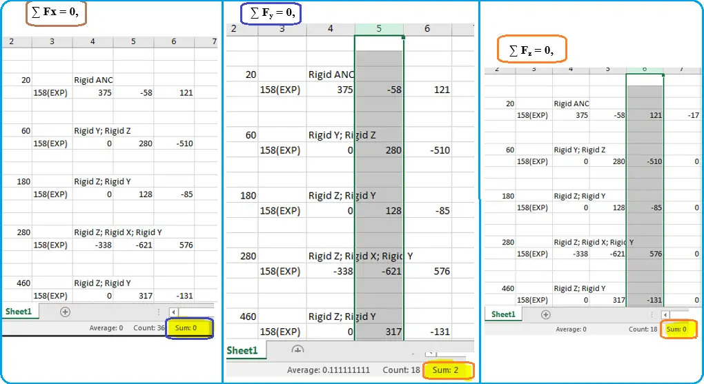
Since the loads are generated in the system itself, the sum of all restraints will be zero in case of a secondary load.
No external load = no net force on the system. The below image (Fig. 6) shows the net forces due to expansion in a piping system.
Another main characteristic that differentiates Primary and secondary load is “Self-Limiting” behavior, which is explained below.
Self-Limiting Behavior
The stress-strain curve of a typical ductile material is shown below in Fig. 7.
Point A – Proportionality limit, till this limit only Hooke’s law is applicable. Hence, OA is a straight line
Point B – Elastic limit, till this point material will exhibit elastic property, AB is non-linear. i.e. Young’s modulus depends on the strain.
Point C & D – Upper Yield Point and Lower Yield point respectively. Most of the materials don’t exhibit upper yield point C. Point C is depending on loading and unloading conditions. Hence, Point C can’t be taken as a yield point. Point D is the yield point of the material which is independent of loading and unloading conditions.
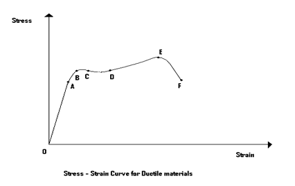
Point E – Point E is the ultimate limit of the material. The increase in Stress after point D is due to the phenomenon of “Strain Hardening”
Point F – F is the failure point of the material. After Point E, necking formation will happen and the material will break into two halves.
All the codes of ASME and B31 approximate the material as “Elastic-Perfectly Plastic” by neglecting Strain hardening and all other irregularities in the curve. The material model used to derive the allowable limit for ASME and B31 code is shown below in Fig. 8.
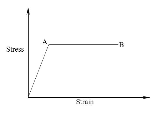
- Point A – Proportionality and Yield limit (Point A, B, C, D, E in the real curve).
- Point B – Failure Limit (Point F in the real curve)
Primary load behavior:
At the start, Stress and strain will be zero (neglecting residual stresses). When we apply the external load “P”, stress will increase which depends on the geometric property (A) and strain also. Now let us take the stress is reached point “A”. After point “A”, an infinitesimal increase in load will create a gross deformation up to the failure point “B”. This gross deformation should be avoided. Here, from Point “A” to “B”, no intermediate strain is possible. After point “A”, point “B” will be reached instantaneously. This behavior is called “load-controlled” behavior. This gross deformation is the failure mode due to primary loads.
Secondary Load behavior:
In the heated bar example, the stress will be generated by constraining the expansion of the bar. When this stress exceeds Point “A” yielding will occur, but no gross deformation will happen like primary. Because deformation or strain is depending on external factors i.e. Temperature difference. Intermediate points between A and B are possible in secondary loads. This behavior is called the “Strain or Displacement controlled” condition. Since gross deformation is not happening in secondary there are other modes of failure related to secondary loads.
With the understanding of Primary and Secondary load, we will try to answer the following self-evaluation (We let the readers discuss the answer in the comments section)
In Stress analysis using CII, I have wrongly entered E= 203200 MPa instead of E=126300 MPa
- What will be the effect on Primary Stress and Deflection?
- Stress will increase and no deflection change
- Deflection will increase and no stress change
- Both deflection and stress change
- Both deflection and Stress will not change
- What will be the effect on Secondary Stress and Secondary Load?
- Stress will increase and no Load change
- The load will increase and no stress change
- Both stress and load will increase
- Both stress and load will decrease
Till now we have seen what is primary and secondary loads and the difference between them. Click here to learn the specific differences between primary and secondary loads in a tabular format.
Now we will explain the failure modes due to primary and secondary loads in a Pressure Vessel and Piping system.
Failure Modes and Allowable Stresses
- Burst due to Pressure (Primary Load)
- Collapse due to weight (Primary Load)
- Elastic Shakedown (Secondary Load)
- Ratcheting (Secondary load)
- Fatigue
Burst Due to Pressure:
When a system is subjected to pressure, stresses developed in the system are
- Longitudinal stress
- Hoop Stress
- Radial Stress
In these, radial stress is neglected in thin wall vessels like piping and pressure vessels.
Longitudinal and hoop stresses are acting in each and every part of the system as shown below in Fig. 9.
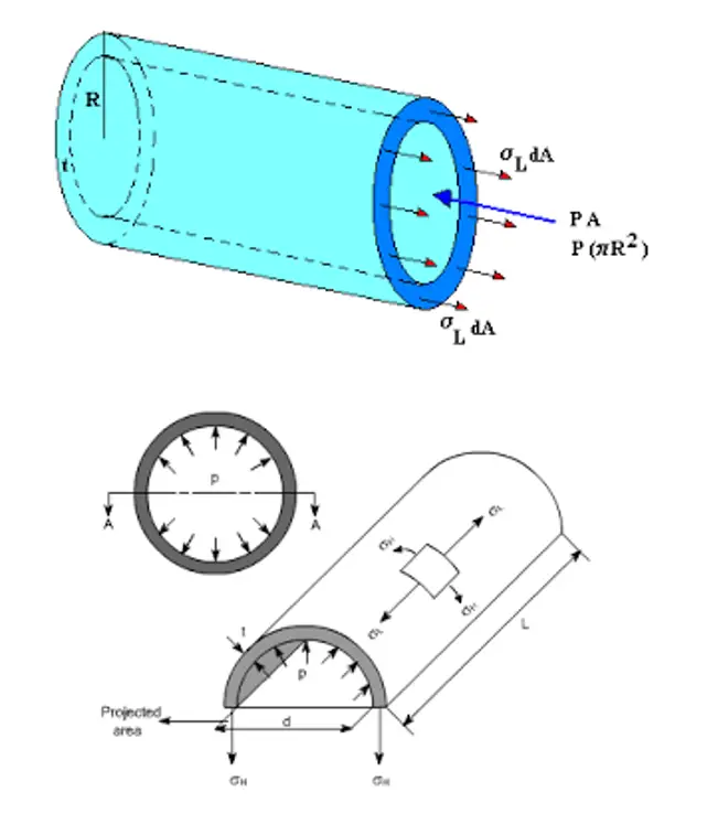
When pressure exceeds the allowable limit burst or excessive straining of the component occurs. Excessive straining implies an unacceptable distortion of the part. Hence, allowable stress for pressure load = Sy
The stress distribution is uniform across the cross-section. Hence, all fibers will yield at once.
Collapse due to weight:
Failures where weight type loads are excessive causing collapse or excessive straining of the component. Since weight load will induce local stresses in the piping system allowable weight-induced stress can be 1.5 Sy. The stress distribution is varying across the cross-section and is maximum at the outer fiber.
Elastic Shakedown:
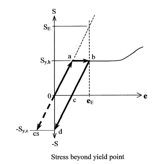
Since elastic shakedown failure is related to secondary loads (displacement loads), there won’t be any gross structural deformation. The below example will explain the allowable stress for Shakedown.
At the start of the system, the material has no thermal stress and strain (Point 0) and now the material gets heated. Expansion is constrained by supports and the system will get stressed. Even if the system is stressed beyond yield, the thermal load is displacement controlled, so there won’t be any gross structural deformation like pressure or weight loads.
Now the material reaches “Point b” which is in the plastic state. After the sometime system is cooled down and the stresses are reduced. When stress came to zero “Point c”, some residual strain will be there. Because of the plastic deformation and when the system comes to its original position i.e. zero strain (point d), stresses in the system will get reversed. Now the system is again heated and stressed. This time there won’t be any plastic deformation. The system will operate in the line “bcd”. The system was brought back to an elastic condition after some initial plastic deformation. This behavior is called “Elastic shakedown” or “Shakedown to elastic behavior”. If we notice the diagram clearly, all these shakedowns will happen only if
Repeated secondary stress = Syc + Syh = 1.5Sc + 1.5Sh (as per B31 allowable criteria)
Where Syc = Cold yield stress and Syh = Hot yield stress
If the allowable stress exceeds these values, plastic hinges will form and gross structural deformation will take place
Ratcheting:
The typical ratcheting model involves axial, non-repeating stress (WNC stress), with a superimposed repeating bending stress (Expansion stress). The combination of repeated bending stress and non-repeated axial stress produces a plastic deformation in the outer fibers that increases with each application of the bending load. Ratcheting-type failure was studied by Bree in a beam subjected to constant axial force and repeated secondary bending moment. The Bree diagram is shown below in Fig. 12.
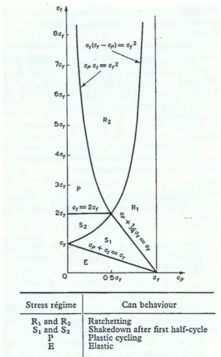
- Horizontal axis = Constant primary stress
- Vertical axis = Variable secondary bending stress
ASME B31 codes have an allowable of 2/3 of Sy for primary stress. For 2/3Sy primary stress, from the bree diagram maximum allowable variable secondary bending stress = 1.33*Sy; i.e. Sum of Primary and secondary stress = 2Sy.
Allowable for ratcheting Sa = Syc + Syh = 1.5Sc + 1.5 Sh = 1.25Sc + 1.25Sh (Taking FOS)
Allowable stress for primary stress (SL)= Sh
Allowable for ratcheting Sa = 1.25Sc + 1.25Sh – Sh = 1.25Sc + 0.25Sh
If SL < Sh , Sa = 1.25Sc + 0.25Sh + (Sh – SL) (Liberal Stress)
The simple ratcheting requirement gives us exactly the same limitations on repeated bending stresses as the shakedown requirement, and the same limitations on the constant axial load as the collapse requirement.
- The Ratcheting limit is the average of Syc and Syh
- The shakedown limit is also the average of Syc and Syh
- The Shakedown limit only uses secondary loadings. The ratcheting limits include primary, (non-cyclic) loadings combined with secondary (cyclic) loadings.
- Shakedown failure can happen in a single cycle, but ratcheting requires a number of cycles to failure.
Fatigue:
Peak stresses are the main reason for fatigue failure. Peak Stresses are those stresses that exist at notches, welds, and other very local stress Concentrations. Fatigue failure is characterized by “peak stress” and “No. of cycle”
B31 allowable for against fatigue protection is
Sa = f (1.25Sc + 0.25Sh)
f = fatigue strength reduction factor, which can be taken from the curve given in B31 codes. As per B31 codes, up to 7000 cycles system will not fail by fatigue. Hence, f = 1, for cycles less than 7000.
Stress Classification in ASME SEC VIII
B31 codes didn’t classify based on the area at which stresses are acting. BPVC has one more stress classification which is based on the area in which stress is acting.
- Classification by Area
- Classification by type of load
Types of Stresses based on area:
Stresses in piping and vessels are divided into three types depending on the location at which it is induced.
- General
- Local
- Peak
Let us have a question:
Which one of the following is dangerous?
- Piping system is pressurized until the material reaches the yield
- The piping system is subjected to a bending load until the material reaches a yield.
To answer the above questions with the reason we will take an example as shown in Fig. 13.

The above diagram shows the loading and stress distribution of a bar subjected to a load “P”. All fibers in the bar are experiencing the same stress “σ”. Now the load is increased till the “σ” value reaches the yield point of the material. Load at which material reaches its yield point is noted as “Py1”. Then a significant deformation that can be seen with the naked eye will take place. Finally, the material breaks. This type of stress is called “General Membrane” stresses. i.e. all the fibers in the system will reach the yield point at the same time e.g. Pressure.
Now the same bar is fixed at one end and a Load “P” is applied on the other end as shown in Fig. 14.
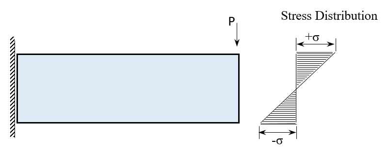
If the load “P” is increased until the outer fiber reaches the yield point, then nearby fibers get overstressed. Once all the fibers till neutral fiber get yield, gross deformation will take place. The load at which gross deformation takes place is “Py2”. This “Py2” is 1.5 Py1. This type of stress is called “Local Stress”. These local stresses will act in areas in the order of (RT)1/2.
Now we will put a small notch (Fig. 15) in the bar subjected to axial load “P”

The stresses near the hole will reach the yield point first. Because the stress-acting region is very small (in part of thickness), failure will not happen. Plastic deformation around the hole occurs and the loads are distributed to the nearby fibers. Since the hole is in part of thickness these types of stresses will not cause any gross structural deformation. But in fatigue loading, cracks will initiate at these locations first. This type of stress is called “Peak Stress”
By understanding “General”, “Local”, and “Peak” it is clear that not only the magnitude of stress only defines the failure, but the area at which stress is acting is also important.
Note that if General stress is “σ” then, Local stress at structural discontinuity = σ + stress rise due to discontinuity
Peak Stress at a notch or weld = Local stress + Stress rise due to notch or weld = (Local primary and secondary Stress) * SCF
Where, SCF = stress concentration factor (to be found based on experiments) ASME BPVC stress classification and its allowable are given in Fig. 16.
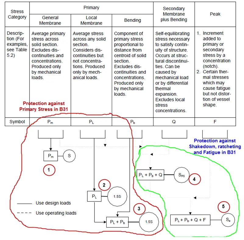
Difference between ASME B31 and BPVC stress classification and allowable
There are five conditions in the BPVC Code. These five conditions are simplified into two conditions in B31 codes.
B31 codes are simplified versions of BPVC codes.
Failure due to primary Loads:
Condition 1: #1 provides protection against General Primary Stress like mechanical loads, and pressure loads.
Condition 2: #2 provides protection against Local Primary Stress like stresses due to mechanical and pressure loads at the nozzle-vessel junction, Plate attachments, etc.,
Condition 3: #3 provides protection for Local Primary combined with Bending. Since bending is local stress it is combined with other local stresses.
Since B31 codes never classified stress as General and Local, #1, #2, #3 are replaced by a single condition; Stress due to primary Loads, SL = Sh
Failure due to Secondary Loads:
Condition 4: #4 provides protection against ratcheting in BPVC codes, which can’t be compared with any of the B31 codes. Because B31 codes include SCF (by the application of SIF), while calculating Ratcheting stress.
Ratcheting Stress in BPVC = Local Primary + Bending + Secondary stresses
Ratcheting Stress in BPVC doesn’t include the effect of the notch or welds.
Condition 5: #5 provide protection against fatigue.
BPVC peak stress = Ratcheting stress * SCF
B31 Peak stress = General (Nominal) stress * SIF
B31 uses peak stress for both ratcheting and fatigue protection. But, BPVC uses different stress for each kind. Click here to know about the Types of Stresses in a Piping System
References and Further Studies:
- Pipe Stress Engineering by L.C.Peng
- ASME Sec VIII, Div.2, Chapter 5
- ASME B31.3
Online Course on Pressure Vessels
If you wish to learn more about Pressure Vessels, their design, fabrication, installation, etc in depth, then the following online courses will surely help you:




Great post, thanks for sharing information.
Thank you for the great information.
What is the allowable local stress of a pipeline system in hydrotest load case based on ASME Sec VIII Div.2?
Hi, I got confused with the first question, or rather, the given answers in which I did not find the correct one: “Deflection will decrease, and primary stress remains unchanged”. Is my answer is correct or not?
Hi, thanks for noticing. My wordings are not clear. I was trying to convey that what will be the deflection when E=126300 GPa compared to E=203200.