Stress Analysis of Buried or Underground piping seems to be difficult for many stress engineers due to the complex soil-pipe interaction. But the software Caesar II easily handles that part. In this article, we will learn the various buried piping analysis methods that are available in Caesar II. The points that will be covered in this article are:
- The various analysis method of Underground piping
- Overview of Soil Classification
- Discuss the current practice of Underground pipe modeling & analysis
- Examine the data inputs for buried piping and pipeline stress analysis
- Make a suggestion for sound input data, especially where information is not known or available
- Learn the inputs, generate some results & conclusions
Caesar II analysis methods for Buried piping
In Caesar II the following four methods are available to perform buried piping stress analysis:
- CAESAR-II Basic method by LC Peng
- American lifelines alliance buried pipe– ALA
- ALA method with 31J
- ALA method with FEA
Soil Classification According to Grain Size
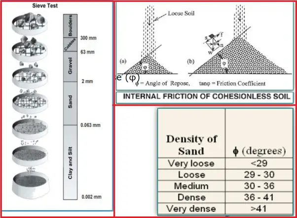
Fig. 1 below provides the soil classification for the most basic soil types used for underground piping stress analysis.
- The most basic classification of soil is based on grain size.
- Soils with large grains are called “gravel” and soils with small grains are “sand”.
- Internationally it is defined that sand contains grains larger than 0.063 mm and smaller than 2 mm.
- Gravel contains grains with sizes between 2 mm and 63 mm.
- Grains smaller than 0.063 mm are called “silt”.
- Grains smaller than 0.002 mm are called “clay”.
Shear Stress in Soils
The ability to resist shear stresses depends on friction and cohesion.
When cohesionless soils are poured to the ground from above they will spread due to gravity. Because of friction, the area of spread is limited creating an angle of repose (φ) at the balanced state.
- From this experiment, the friction force that resists the shear loads may be calculated and the internal friction coefficient (µ) of the soil may be determined:
f = µ ⋅n = µ ⋅w⋅cosϕ —-where f=wsinϕ
µ = tanϕ
- The friction resistance (s) of any soil in any plane is then expressed as Sliding force ( s ) + Cohesion ( c )
s = n⋅tan(ϕ) + c
The angle (φ) is also called the soil angle of internal friction.
Axial Soil Resistance
- Frictional Force on the Top of the Pipe and at the Bottom Of the pipe are different
- In the case of an idealized model the axial resistance (f) can be determined by the following expression:

Lateral Soil Resistance
- Lateral Soil Resistance is divided into 3 parts viz. Upward, Downward and Sideways
Upward Resistance (Fig. 3):
Upward soil resistance can be described by the application of the “soil prism theory” also known as “Marston’s load theory”! This theory states that the soil resistance is determined by (a) the weight of a soil prism above the pipe and (b) the shear forces exerted on either side of the prism. ! The shear conditions depend on the installation layout of the pipe and soil, but in this case, negative shear will be assumed. ! Next to the soil prism, the weight of the pipe needs to be taken into consideration as well.
Shear stresses can be found by integrating the friction along both side surfaces of the prism.
Let’s assume cohesionless soil (c=0, e.g. sand); ϕ is the friction angle of the soil.
q = Wt. of Soil Above Pipe + Shear Resistance + Wpipe
q = ρDH + 2H (c + 0.5 ρ H Ka tanФ) + Wpipe = ρDH + ρH2 Ka tanФ
Downward Resistance (Fig. 3):
- When the pipe moves downwards the soil resistance can be determined from the “vertical bearing capacity”.
- Detailed geotechnical evaluation is required to determine the vertical bearing capacity.
- For a general idea, the downward resistance can be roughly estimated to be as twice the horizontal resistance. ! The vertical bearing capacity is the vertical load required to break the soil underneath the pipe over the full width of the pipe.
Horizontal Resistance (Fig. 3):
When a pipe moves horizontally, it experiences
- Passive Force from Front
- Active Force from Back
Active force is ineffective as the pipe moves and a void is created.
qh = ½* ρ (H+D)2 tan2 (45 + Ф/2)
For cohesive soil (clay) ф = 0, hence less resistance

How Caesar II models soil?
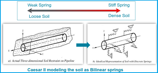
- Soil is modeled as a ‘Bilinear Spring’ having ‘initial stiffness, ultimate load, and Yield Stiffness’
- Ultimate load: Maximum load on the soil beyond which load does not increase but displacement can.
- Ultimate loads are different in axial, lateral, and vertical directions
Modeling Soils in Caesar II
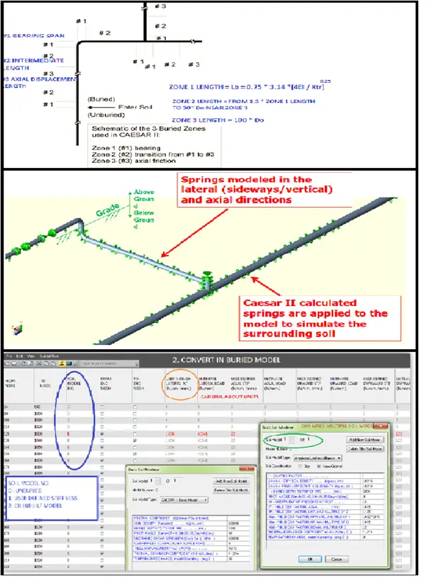
Caesar II simulates the soil surrounding the pipeline using springs of varying stiffness as shown in Fig. 4.
About CII Buried Pipe Modeler
Refer Fig. 5
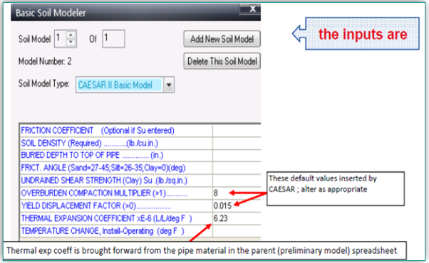
CAESAR-II Basic method by LC Peng
American Lifelines Alliance-ALA
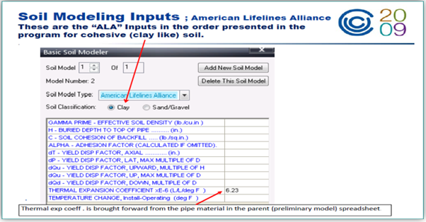
ALA method with 31J
B31J provides a set of calculations for revised SIFs and flexibility factors, as defined in the upcoming revision to ASME B31J. By using these revised SIFs and flexibilities, your stress analyses produce more accurate results. B31J provides the “more applicable data” referenced in recent editions of the piping codes.
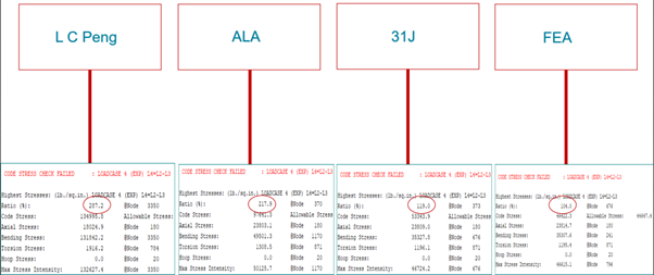
Result Comparison with Various method:
Conclusions
- Results obtained by ALA Method are more reliable
- ALA considers more variables based on published data
- Better method if the soil is changing through the run
- Peng’s Method gives a very good understanding of the subject and gives quick results for non-critical
- If the buried pipe is modeled just as a reference in the Above ground Piping Analysis then suggested going for the ‘CAESAR II Basic Model’
- For Pipeline analysis use ‘ALA Method with user-defined stiffness input
Online Buried Pipe/Pipeline Stress Analysis Course
You can attend an online course on buried/underground pipe/pipeline stress analysis that covers the underground pipe stress analysis details using a practical case study by clicking here.
Author: This presentation is prepared by Mr. Deepak Sethia who is working in ImageGrafix Software FZCO, the Hexagon CAS Global Network Partner in the Middle East and Egypt. He has extensive experience in using Caesar II and PV Elite software and troubleshooting.
Few more Related articles for you.
Basics for Stress Analysis of Underground Piping using Caesar II
Underground Piping Stress Analysis Procedure using Caesar II
Few Salient Points for Underground / Buried Piping
Training Video: Buried/Underground Piping Stress Analysis
Buried GRP/FRP pipe Laying and Installation Procedure
STRESS ANALYSIS OF SURFACE LAID PIPELINES
What if Piping Continuation is Unknown? Part 2. Underground Piping

Dear Anub
When the ALA method with B31J or FEA is use, Do you use the soil modeler first an then FEA translation or fist FEA and the soil modeler?
When the ALA method with B31J or FEA is use, Do you use the soil modeler first and then FEA translation or fist FEA and then soil modeler?.
How to protect burried pipe subject to temp. changes.?