Flange leakage checking is a very important activity in pipe stress analysis. Flange leakage checking ensures that there will be reduced chances of flange leakage. There are various methods available for flange leakage checking in conventional stress analysis software packages like Caesar II. NC 3658.3 method is one such popular flange leakage checking method. In this article, we will discuss the step-by-step methods for performing flange leakage analysis using the NC 3658.3 method in the software Caesar II.
NC 3658.3 provides a flange leakage evaluation method based on the NC code for ASME B16.5 flanges using high-strength bolts. Caesar II software has a nice module in its input spreadsheet to use this method efficiently and with ease. In the following paragraphs, I will describe the methods of flange leakage evaluation by NC 3658.3 method using Caesar II.
Criteria for NC 3658.3 Method Application
NC 3658.3 Method for flange leakage evaluation can only be applied if the following two conditions are met:
- Flanges, bolts, and Gaskets used are designed based on rules as specified in ASME B 16.5 and
- Bolting material must have an allowable stress value at 100°F(38°C) >=20000 psi (138 MPa) (High Strength Bolting)
Governing Equations as Per NC 3658.3 method
By NC 3658.3 method the generated external moment (Mfs) is limited to a value as provided by the below-mentioned equation:
Mfs<=3125(Sy/36000)C X Ab (in U.S. Unit);
Here
- Sy=Yield strength of flange material at the temperature
- Ab= Bolt area
- C=Bolt Circle Diameter
- The ratio of Sy/36000 has to be taken less than unity.
So it is obvious from the above equation that we have to enter the bolt area, bolt circle diameter, and flange material yield strength as input into Caesar II Spreadsheet for flange evaluation using the NC method.
Flange Evaluation steps followed in Caesar II
- Select Flange Node (From/To/Both) and Calculation Type (NC-3658.3) as shown in Fig. 1.
- Input Bolt circle diameter from ASME B 16.5.
- Input Yield Strengths at the temperature from ASME BPVC code Section II Part D Table Y1.
- Calculate the Bolt Area (Ab) as shown below and input it in the required place:
Bolt area, Ab is the total cross-sectional area of the bolts at the root of the thread or section of least diameter under stress.
Bolt Area Calculation for NC method
Calculate the bolt area as mentioned below
Droot = D1bsc – 2*0.21650635P & D1bsc = Dbsc – 2*h
Where
- Droot = Root diameter of the bolt
- Dbsc = Basic major (nominal) diameter of bolt (as per ASME B1.1, para 8.3)
- D1bsc = Basic Minor diameter (as per ASME B1.1, para 8.3)
- h = Height of thread (as per ASME B1.1, Table 5)
- P = Pitch of Bolt (as per ASME B1.1, Table 1)
Root Area of bolt (Ab) = n x [(pi/4)* Droot2)]
Where n = No. of bolts as per flange pressure rating class
Alternately, The bolt area can be directly taken from ASME PCC-1, Table H-1/H-1M for inch series and metric threads respectively.
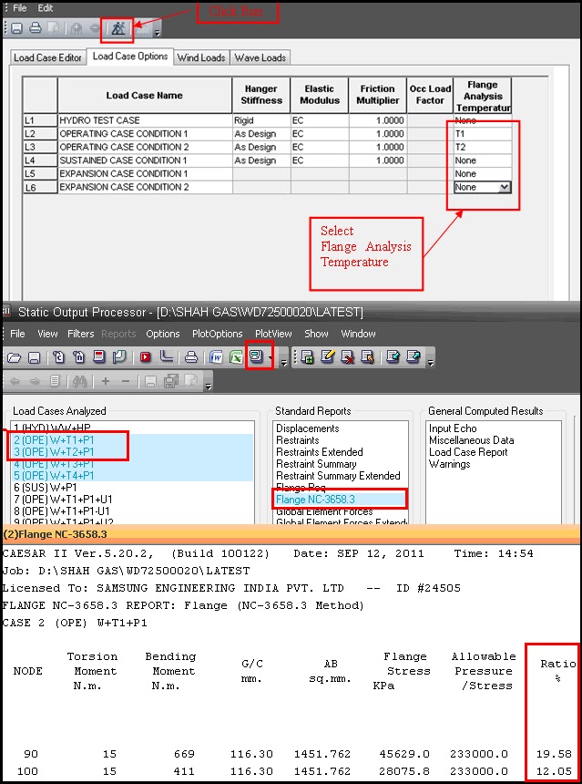
Now go to the Load Case Option Editor (Fig. 2), select flange analysis temperature based on operating/design conditions, and click the Run button for analysis.
Select the Load Case(s) for which Flange Leakage Check has to be performed and see the results. If the ratio of Flange Stresses to Allowable Stress is less than 100 % (See Fig. 2), Then the flange is within the allowable limit and should not produce leakage. If it is more than 100%, Then try to reduce moments at the flange by re-analyzing the system and then re-check using the above method.
Allowable Stress for NC 3658.3 method as per Caesar II
Caesar II Allows the user to check the NC flange leakage check at 9 temperature case conditions (operating condition ), Hydrotest, and Sustained condition at a time.
In CAESAR II, an Equivalent flange Stress S is calculated based on the following formulas, and then the calculated stress is compared to Sy (or 2*Sy for occasional load cases), in the following manner:
S = 36,000* Mfs / (CAb * 3125) ≤ Min(Sy, 36000) (non-Occ)
S = 36,000 * Mfd / (CAb * 3125) ≤ 2.0 * Min(Sy, 36000) (Occ)
Note that both the above equation is in the FPS unit. For metric or other unit systems, the Caesar II software converts the 36,000 values in the above equations to the appropriate set of units.
Is the NC 3658.3 method applicable for ASME B16.47 Flanges?
The specific clause of NC3658.3 clearly states that the method is only applicable for ASME B16.5 flanges. So, in general, the method is applicable for flanges up to 24″ sizes. However, piping engineers frequently encounter piping systems having sizes greater than 24 inches means flanges from the ASME B16.47 standard. Several studies have already been done regarding the applicability of the NC 3658.3 flange leakage checking method for ASME B16.47 flanges.
One such published paper with the title “Use of NC 3658 flange design rules for ASME B16.47 flanges- An analytical and finite element based study” by Anindya Bhattacharya & Michael P Cross concludes that the simple method of checking a flanged joint based on NC 3658.3 can be extended to B16.47 flanges, but there are some exceptions as mentioned below:
- NC 3658 flange design rules are not applicable for flanges of size 60 inches 600 Lb.
- Also, for sizes >=36 inches, 600 Lb. and higher flange ratings, as the operating stress on bolts is higher than twice the material allowable stress, the NC 3658 rules are not applicable.
For more details, you can refer to the paper from the following site: https://asmedigitalcollection.asme.org/ESDA/proceedings-abstract/ESDA2014/45837/V001T05A009/232054


is flange leakage done for cold piping ?
Yes..for both cold piping and hot piping flange leakage need to be performed..
What is the criteria for flange leakage of cold lines?
Criteria should be based on ITB document..I dont feel it will defer from hot lines…In short you can check/ investigate for leakage possibilities in the following cases:
1. On control valves
2. On PSv connections
3. On other connections where leakage can cause serious harm to mankind
Roughly you can check all locations where bending stress near to flanges are more than 4000 psi.
Dear Anup,
Kindly share your whatsup number for asking more Stress related questions?
Guys, I am creating Whatsup Group for Stress Analysis member ?
Please share your phone number to my what’s up number +91-99678-12330
hello sir in flange leakage evaluation method NC 3658.3 in result if ratio is more than 100% how to change the moments explain in detail
regards
rizhwan md
Hi all,
This site has been so helpful, word cannot express my gratitude to the facilitator for a job well done.
Thanks alot
Dear Sir,
I come from the middle east region which is not a very seismic prone zone. I am performing flange leakage using the NC method. I wanted to enquire if flange leakage needed to be performed for the wind and seismic cases as well??
Flange leakage is normally not checked for wind and seismic cases. However if your client says to do so you don’t have other option.
Hi Good Evening Every Body,
I have Query Regarding NC 3658.3 Result, I notice that in some cases when i am checking flange leakage for higher flange size in output of flange leakage area of bolt (AB sq mm) is showing ***** Value in SI units. if you run same file in US unit than AB sq Inch value is there. so My Query is why it happen.
because the value is too large.
CAESARII will show **** for very large values (Forces, Moment, Stress, etc)
Hi Anup, thank you for your article, Where did you get the Droot = D1bsc – 2*0.21650635P & D1bsc = Dbsc – 2*h formulas? I tried to get information about that but I didn´t find anything, coud you please refer to a book, standard or article to read more about it. Thank you in advance
Hi Anup,
Thanks for the helpful website,
According to NC-3658, we have another limitation for using this method:
Used where neither the Design nor Service Pressure exceeds 100 psi and neither the Design nor Service Temperature exceeds 200 F.
Is it correct?
Hi Anup,
Thanks for the helpful website.
According to NC-3658.3, we can use the NC method if the Design pressure or Service Pressure is lower than 100psi and the design temperature or the service temperature is lower than 200 F.
Is it correct?
Hello I have a question. Can flat face flange also be assessed based on NC3658.3?
ASME SECTION III – NC-3658.3 has specified two limits for checking flanged joints. The first limit checks pressure “ The pressure shall not exceed the rated pressure for Level A Service Limits or 1.1 times the rated pressure for Level B Service limits”.
The second limit studies bending or torsional moment. However, it seams CAESAR II only check the second limit.
The question is how CAESAR II considers pressure effect in flanged joint checking procedure by NC-3658?