
Compressors are mechanical devices that increase the pressure of gases by reducing their volume. They are essential in a wide range of applications, including oil and gas industries, chemical and petrochemical industries, HVAC systems, industrial processes, and transportation. The choice between centrifugal and reciprocating compressors can significantly impact efficiency, cost, and operational performance. This article aims to comprehensively compare these two compressor types, helping readers understand which might be more suitable for their specific needs.
What is a Centrifugal Compressor?
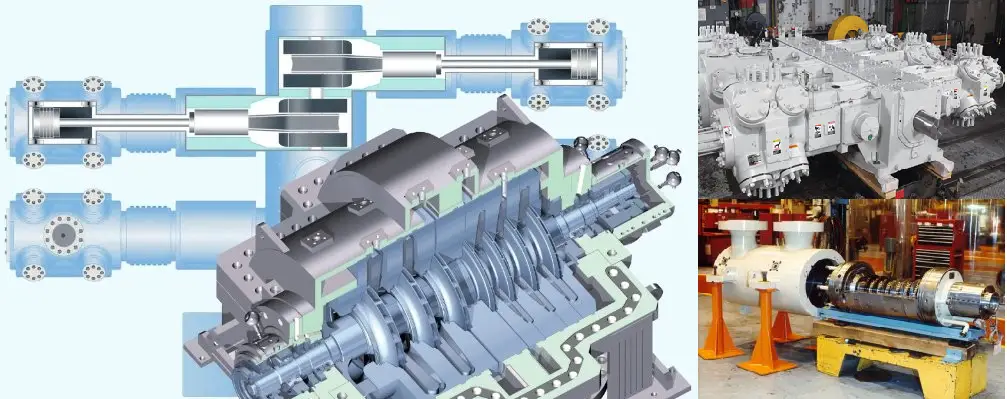
A centrifugal compressor is a dynamic compressor with a radial design. The gaseous fluid enters the center of a rotating impeller with radial blades and is pushed toward the center by centrifugal force, which results in a rise in pressure and increases in kinetic energy. This energy is then converted into pressure by passing through a diffuser and volute. A centrifugal compressor is popularly used in Process Industries, Oil and Gas, Refineries, Wastewater treatment plants, etc. Single- or Multistage compressors are used depending on specific applications and industries.
Centrifugal compressors consist of a rotating impeller and a diffuser. The impeller, which is usually made of materials like aluminum or steel, rotates at high speeds, drawing in gas through the inlet. As the gas moves through the impeller, it gains kinetic energy, which is then converted to pressure energy in the diffuser.
Key Components:
- Impeller: The heart of the compressor, responsible for adding energy to the gas.
- Diffuser: Converts kinetic energy into pressure by slowing down the gas flow.
- Volute: Collects the compressed gas and directs it toward the discharge.
For more details about Centrifugal Compressors Click here
What is a Reciprocating Compressor?
A reciprocating compressor is a positive-displacement compressor that uses a cylinder and piston mechanism to compress the gas. The gas in the inlet section is compressed by the reciprocating motion of the pistons. Reciprocating compressors are used in refineries, gas pipelines, chemical and petrochemical plants, natural gas processing plants, and refrigeration plants.
Reciprocating compressors operate using a piston mechanism within a cylinder. The piston moves back and forth, creating a change in volume that compresses the gas. These compressors can be single-acting or double-acting, depending on whether the gas is compressed on one side or both sides of the piston.
Key Components:
- Cylinder: Houses the piston and creates the compression chamber.
- Piston: Moves to compress the gas.
- Crankshaft: Converts rotational motion into the linear motion of the piston.
- Valves: Control the intake and discharge of gas.
Click here to know more about Reciprocating Compressors
Difference between Centrifugal and Reciprocating Compressor
The major differences between centrifugal compressors and reciprocating compressors are provided below:
Differences in operating principles
Centrifugal Compressors
Centrifugal compressors operate based on the principles of fluid dynamics. The rotating impeller accelerates the gas, converting its velocity into pressure through the diffuser.
Steps in Operation:
- Gas Inlet: Gas enters the impeller.
- Acceleration: The impeller spins, imparting kinetic energy to the gas.
- Pressure Conversion: The diffuser slows down the gas, converting kinetic energy into pressure.
- Discharge: The high-pressure gas exits through the volute.
Reciprocating Compressors
Reciprocating compressors utilize the mechanical motion of a piston to compress gas.
Steps in Operation:
- Intake Stroke: The piston moves down, creating a vacuum that allows gas to enter the cylinder.
- Compression Stroke: The piston moves up, reducing the volume and increasing the pressure of the gas.
- Discharge Stroke: The discharge valve opens, allowing high-pressure gas to exit the cylinder.
Differences of Reciprocating Compressors and Centrifugal Compressors in Performance Characteristics
Efficiency
Efficiency in compressors is a critical factor that affects operational costs and energy consumption.
- Centrifugal Compressors: Generally exhibit high efficiency at large flow rates and are better suited for continuous operation.
- Reciprocating Compressors: More efficient at lower flow rates but can become less efficient at high flow rates due to the mechanical complexities involved.
Pressure Ratio
The pressure ratio refers to the ratio of the discharge pressure to the inlet pressure.
- Centrifugal Compressors: Typically achieve high pressure ratios, making them suitable for applications requiring significant pressure increases.
- Reciprocating Compressors: Can achieve higher pressure ratios but usually require multiple stages to do so effectively.
Capacity Control
Capacity control is essential for adapting to varying demand.
- Centrifugal Compressors: Often employ variable speed drives or inlet guide vanes for capacity control.
- Reciprocating Compressors: Use unloading mechanisms, such as suction throttling, to control capacity.
Differences in Applications
Centrifugal Compressors
Centrifugal compressors are widely used in applications that require a continuous supply of gas at high flow rates. Common applications include:
- HVAC Systems: Used in large chillers for cooling.
- Gas Processing: In the petrochemical industry for gas transport.
- Power Plants: For air supply in combustion processes.
Reciprocating Compressors
Reciprocating compressors are versatile and can be found in various applications, including:
- Refrigeration: For both domestic and industrial refrigeration systems.
- Gas Transportation: Used in natural gas pipelines for pressure maintenance.
- Automotive: Employed in air conditioning systems in vehicles.
Differences between Centrifugal and Reciprocating Compressors in Terms of Advantages and Disadvantages
Centrifugal Compressors
Advantages:
- High Efficiency: Especially at large flow rates.
- Simple Design: Fewer moving parts, leading to lower maintenance needs.
- Continuous Operation: Suitable for applications requiring constant airflow.
Disadvantages:
- Limited Pressure Range: Less effective at low flow rates.
- Cost: Typically higher initial investment compared to reciprocating compressors.
Reciprocating Compressors
Advantages:
- Versatility: Can handle a wide range of pressures and flow rates.
- High Pressure Capability: Excellent for applications requiring significant pressure increases.
Disadvantages:
- Maintenance: More moving parts can lead to higher maintenance costs.
- Pulsating Flow: May require additional components to smooth out gas flow.
Differences between Maintenance Considerations
Proper maintenance is essential for both types of compressors to ensure longevity and efficiency.
Centrifugal Compressors
- Routine Inspections: Check for wear on impellers and diffusers.
- Lubrication: Ensure proper lubrication of bearings and seals.
- Vibration Monitoring: Regularly monitor vibrations to detect imbalances.
Reciprocating Compressors
- Piston Inspection: Regularly check piston rings and cylinders for wear.
- Valve Maintenance: Inspect and replace valves as needed.
- Oil Changes: Frequent oil changes to ensure optimal lubrication.
Some additional differences between centrifugal and reciprocating compressors based on various parameters like maximum and minimum flow, inlet and outlet pressure, efficiency, compression ratio, discharge temperature, flow range, materials of construction, cost, etc. are listed below.
The comparison refers to the article titled: “What’s Correct for My Application – A Centrifugal or Reciprocating Compressor” by compression equipment specialists of Ariel Corporation: Paul Gallick – Senior Applications Engineer, Elliott Company; Greg Phillipi and Benjamin F. Williams.
The contents of the above article are produced in a tabular manner with minor modifications based on various other sources and the author’s own understanding.
| Parameter | Centrifugal Compressor | Reciprocating Compressor |
| Maximum Flow | They can be sized for an inlet flow of 680,000 actual m3/h in a single body. Actual means at given suction pressure and temperature. The maximum flow through a centrifugal compressor is limited by the choke point, which is the point at which the flow through some part of the compressor nears a velocity of Mach 1. | The capacity of a reciprocating compressor is limited by cylinder size, the number of throws available, and the available driver speeds. A “throw” is a location on the crankcase where a compressor cylinder can be attached. |
| Minimum Flow | It is recommended that for flow rates of actual 300 m3/h and above, centrifugal compressors be critically evaluated for suitability. Unlike a reciprocating compressor where flow is solely a function of compressor geometry and speed, the minimum flow for a centrifugal compressor is limited by an aerodynamic condition known as surge, which is a function of compressor geometry, speed, aerodynamic gas conditions, and system resistance. | Similar to the maximum flow, the minimum flow in a reciprocating compressor is limited by the cylinder size, stroke, and speed. Reciprocating compressors of capacities of a few m3/h are available. |
| Minimum Suction (Inlet)Pressure | This can be atmospheric or sub-atmospheric (vacuum). For sub-atmospheric suction conditions, special seal and buffering designs are employed to prevent atmospheric air from being drawn into the compressor. | Can be atmospheric or vacuum. Where suction conditions involve sub-atmospheric pressures, adequate measures must be taken to prevent atmospheric air from leaking into the cylinder through the piston rod packing. |
| Maximum Discharge (Outlet) Pressure | For horizontally split compressors, discharge pressures up to 100 barg are common. For radially split (barrel) compressors, discharge pressures could go as high as 1000 barg. | Typical reciprocating compressors in the process industry are used to generate discharge pressures as high as 800 barg. Special compressors known as hyper compressors used in low-density polyethylene manufacture will generate pressures as high as 3500 barg. |
| Minimum Suction (Inlet) Temperature | Standard Centrifugal compressor materials are typically suitable for -20 to -50 deg C. Refrigeration compressors in ethylene service typically have temperatures as low as -100 deg C which require special low-temperature alloys. The lowest temperature requirement for centrifugal compressors is typically found in LNG boil-off gas applications. Minimum temperatures up to -170 deg C are required to be accommodated for this service and low-temperature alloy steels are employed as materials. Low-temperature seals and O-Rings are also required. | The common compressor cylinder materials, cast gray iron, and cast ductile iron are acceptable for use at temperatures as low as -40 deg C which typically occur in refrigeration applications. The lowest suction temperatures required typically are in LNG boil-off applications with requirements as low as -170 deg C and there are very limited manufacturers for this application. |
| Maximum Discharge (Outlet) Temperature | Maximum discharge temperatures are typically 200 to 230 deg C. Centrifugal compressors with higher temperatures can be manufactured but would require special designs such as center-supported diaphragms, less efficient seal materials, and high-temperature O-rings and sealants. | Discharge temperature limits will depend on the application (gas compressed) and the seal element materials selected. In hydrogen-rich gas applications, API 618 (2007) limits discharge temperatures to 135 deg C. For natural gas service, the maximum discharge temperature limit is 175 deg C. However, a more practical limit followed is 149 deg C. Air compressor discharge temperature limits may be as high as 200 deg C. |
| Flow Range (turndown) | The flow range of a centrifugal compressor is determined by the surge and choke points. Typical turndown for a fixed-speed, multi-stage centrifugal pump is approximately 20-30%. With variable speed drive or adjustable inlet guide vanes, the turndown can be increased to 40-50%. | Reciprocating Compressors have the ability to change flow through speed control, the addition of fixed clearance to a cylinder (fixed or variable volume clearance pockets), cylinder end deactivation, and gas recycling. The typical flow range might be from 100%, down to 20%, or even lower. The application will determine what type of capacity control method is required and used. On low compression ratio applications (compression ratio less than 1.6, such as pipeline transmission of natural gas) adding fixed clearance will hardly change the flow. Such an application may require speed control or cylinder end deactivation. In other applications with higher compression ratios, clearance pockets and cylinder end deactivation are commonly used to regulate flow. |
| Compression Ratio | For centrifugal compressors, the compression ratio is a function of gas molecular weight, compressibility factor, stage geometry, speed, and the number of compressor stages. For a specific gas, the limits to compression ratio are the mechanical and rotodynamic limitations on speed and the number of stages that can be accommodated in a single body. High discharge temperatures due to high compression ratios can usually be controlled by the intercooling between a compression stage. | The maximum compression ratio that a reciprocating compressor can handle in one stage is limited mostly by gas discharge temperature. The piston rod load generated by the compression ratio may also be a limit. Typical compression ratios for one stage are 1.2 to 4.0. |
| Compressed Gas Molecular Weight | The compression ratio is highly dependent on gas molecular weight. The head is developed by increasing gas velocity to create kinetic energy and then converting the kinetic energy to pressure in the diffuser. The amount of kinetic energy is a function of the gas velocity and gas molecular weight. Centrifugal compressors are used for a broad range of molecular weights including low molecular weight applications such as hydrogen recycling and high molecular weight applications using refrigerant gases with molecular weights over 100. | Reciprocating compressors are not limited by gas molecular weight. Both light and heavy gases are compressed very well. Over the range of molecular weight, different application configurations may be required. For example, very low molecular weight gases may present seal challenges and very high molecular weight gases may present challenges related to compressor efficiency. |
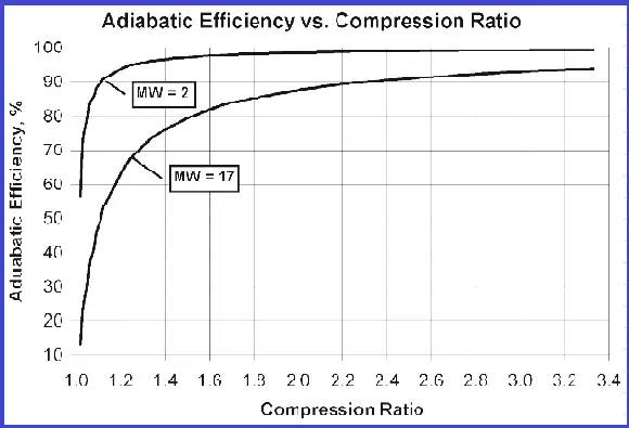
| Efficiency | Polytropic efficiencies are used for centrifugal compressors rather than adiabatic efficiencies. In applications involving air compression adiabatic efficiencies are used. Typical polytropic efficiencies range from 70% to 85%. Efficiencies approaching 90% are possible. Efficiencies are primarily affected by internal leakage and mechanical losses. | Reciprocating compressors have a very characteristic adiabatic efficiency curve. Refer to the figure. As the compression ratio drops, adiabatic efficiency drops. Efficiency changes with molecular weight too. Other factors also impact efficiency, most significantly the compressor cylinder’s ratio of valve flow area to main bore diameter and piston speed. |
| Parameter | Centrifugal Compressor | Reciprocating Compressor |
| Multiservice Capability | Typically, centrifugal compressors are not designed to handle a multitude of gases. Customized designs would be required that could handle different gases simultaneously. | Reciprocating compressors are very adaptable to a multitude of gases and can handle different gases at either the same stage or at different stages in the same machine. The number of different services on a given compressor crankcase (frame) is only limited by the throws available and the number of stages required for each service. 8, 10, and even 12 frames are not uncommon |
| Materials of Construction | Materials for major components such as casings, nozzles, shafts, impellers, etc. are primarily carbon steel, stainless steel, and/or alloy steel. Components may be cast, forged, or machined. Cast iron may be used for some stationary components. Material selection is primarily dependent on temperature, stress (pressure/torque), and gas composition (corrosive/erosive). | Reciprocating compressors are made of very common materials such as gray iron, ductile iron, carbon steel, stainless steel, and alloy steel. This could be in the cast, forging, or bar stock form. Some compressor pistons and covers may be made of aluminum. For corrosive applications, it is common to use stainless steel such as 17-4PH or 400 series for piston rods and compressor valve seats and guards. |
| Cost – Capital and Operating | The capital cost of a centrifugal compressor is typically higher than a reciprocating compressor operating under the same conditions. This is primarily due to the fact that centrifugal compressors require parts with more complex geometry, such as impellers and diaphragms. However, a centrifugal compressor has fewer wearing parts, resulting in lower operating costs in terms of replacement parts, repairs, and downtime. For gas pipeline compression services where large centrifugal compressors (>7500 kW) are employed, using gas turbine drivers becomes economical compared to electrical motors when doing a cost evaluation in terms of capital and operating expenditure. | Generally, a reciprocating compressor will have a lower capital cost but a higher operating cost (excluding power consumption). For the same operating conditions, a reciprocating compressor will consume less power per unit volume flow. The reason for the higher operating costs is due to more wearable parts requiring frequent maintenance and leading to higher machine downtime. Compressor valves happen to be one of the most wearable parts in a reciprocating compressor. |
| Reliability | The reliability and availability of centrifugal compressors are typically 98 to 99%. | The reliability and availability of reciprocating compressors is typically 95 to 98%. Since reciprocating compressors have many more parts and more rubbing seals (pressure packing, piston rings, and rider rings) that wear and require more frequent replacement, they are considered somewhat less reliable than centrifugal compressors. Another reciprocating compressor component is compressor valves (simple spring-loaded check valves) which require frequent maintenance and replacement |
| Typical Maintenance Intervals | In clean gas service and without much variation in operating conditions, a centrifugal compressor can operate continuously for 10 years or longer. Maintenance requirements are typically limited to replacing bearing pads and seal-wearing parts. | Maintenance requirements for reciprocating compressors vary significantly with the application and follow maintenance patterns very much based on what has been described in the reliability section. Compressor valve and seal elements may require to be maintained in durations as short as a few months and as long as 3-5 years. Major machine overhaul including bearing replacement may be required after 10 years of operation or longer. |
| Installation Time and Complexity | The installation time varies widely depending on the size of the compressor. The number of main casing nozzles and the type of driver (electric motor/gas or steam turbine) also affect installation time. Location can also be a factor. Remote or offshore locations can add to installation time. The compressor and driver are typically packaged on a base plate complete with oil piping and wiring to junction boxes. Process equipment such as scrubbers, and coolers and process control valves are typically installed at the site. Auxiliary systems such as lube oil consoles, control panels, and seal buffer systems may also be installed separately. Piping and wiring from these auxiliary systems and process equipment to the compressor train are typically done at the site. Installation time for a typical motor / gear-driven compressor package is 2-3 weeks. For a very large compressor or a gas turbine-driven compressor, the installation time could be as high as 6-8 weeks. | Installation time for a reciprocating compressor varies significantly with site and location, and whether or not the compressor is packaged. Packaged compressors up to 3.4 MW and of a high-speed short-stroke design are common today. Installation time for these might vary from a few days to a couple of weeks. Larger slow speed long stroke compressors assembled at the site might require 3 to 4 weeks to install |
| Lead Time | Lead time for a centrifugal compressor train range from 35 to 75 weeks. Often the lead time is governed by the driver (electric motor/turbine) since these are generally made to order. Special metallurgy and/or special design requirements of compressor components significantly add to the lead time. | Lead time for a bare compressor will vary from 14 to 40 weeks depending on size and manufacturer. Electrical motor-driven reciprocating compressors may require longer lead times specifically if large high-horsepower motors are required. For reciprocating gas engine-driven large compressors the lead times may be shorter |