
A discontinuity occurs where there is a sudden change in material, geometry, or loading. The behaviour of different free components, such as their displacement under a specific load, may be different. However, when they are connected, they cannot move freely. This restriction of movement creates stresses, which are referred to as discontinuity stresses.
Beams on Elastic Foundation Theory
Beams on Elastic Foundation theory is used to evaluate the discontinuity stress. Figure 1 shows an infinitely small beam element placed on an elastic foundation.
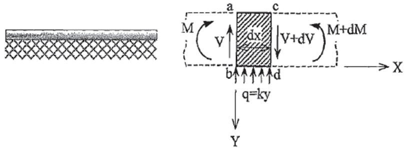
As it is shown, the distributed force q, acts upwards in response of the downward displacement of the element.
q=ky,
Where:
K is the spring constant per unit length
y is the vertical displacement of the element
Force and moment equilibrium of the element show in the Figure 1 is as follows:

The second order of very small quantities can be ignored, so:
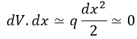
Therefore:

Combining Eqs. 1 and 2:

The displacement made by shear force is insignificant in a slender beam. Thus, it can be assumed that the displacement is completely due to bending moment.

Combining Eqs. 3 and 4:

The equation 5 can be solved if y=eex, where α is an exponent constant that must be determined. Differentiating eαx four times with respect to x and substituting y, we have:

From Eqs. 5 and 6:
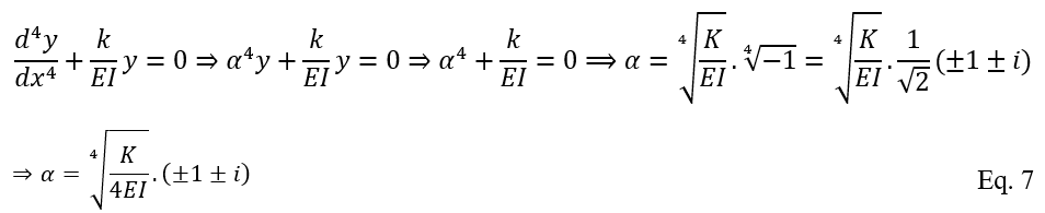
The answers of Eq. 7 are:
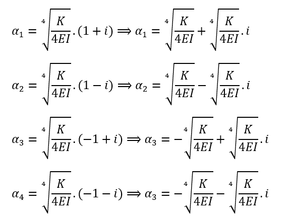
By considering the characteristic factor β=4√(k/4EI), and since y=eex, we obtain:

and:

Where A, B, C, and D are integration constants. By performing some mathematical manipulation, we have:

Determination of the integration constants C1, C2, C3, and C4 depends of boundary conditions of the beam. This equation is used to solve some of the discontinuity stress problems in the piping field.
Using Beam on Elastic Foundation in Cylindrical Shells
The beam on elastic foundation theory can be used for evaluation of discontinuity stresses of a thin-wall cylindrical shell.
Before conducting any calculations, it must be shown that the behaviour of shell is similar to that of a beam on an elastic foundation. Once it is established, the spring constant can be used in the further calculations. With respect to the Figure 2, we have:
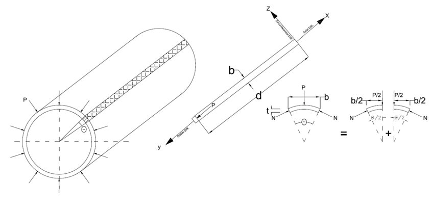
The radial load P is uniformly distributed along circles perpendicular to the axis of the cylinder. The loading is symmetrical; so, the section will remain circular. The load P moves the shell by a distance y towards the center. The magnitude of the radial displacement decreases from y to zero as the distance from the point load increases along the axial direction. This change in displacement creates bending stress in the shell. Since the cross-section and loading are symmetrical, it can be assumed that the situation is similar to that of a longitudinal strip of unit width, b.
The load reduces the radius of the cross-section and its circumference. Further calculations evaluate the circumferential strain (εc), the circumferential compressive force (F), and the support force per unit length (P).

Based on the Eq. 11, the Circumferential Compressive Force per unit strip length (N) is:

In addition, the width of the strip, b =r.(Theta). So:

Applying force equilibrium, combining Eqs. 12 and 13, and considering b = 1, we obtain:

As shown, P is proportional to y. Therefore, the strip can be considered as a beam on an elastic foundation. Thus, the spring constant for the unit width is:

According to Figure 4, if the element is free to move along the Z direction, the bending moment will cause a strain in the Z direction (εZ).
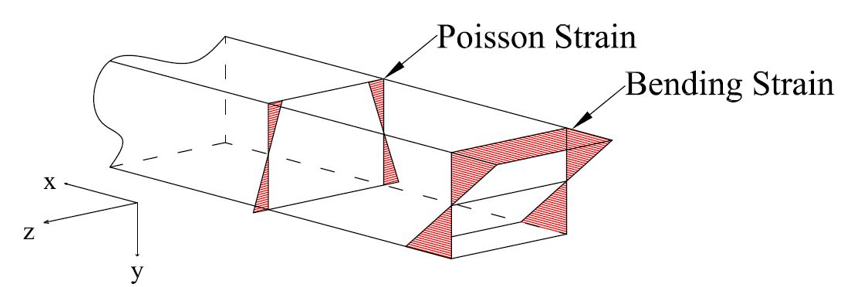
In a cylindrical shell, the cross-section remains circular. Thus, the εZ equals to zero. In addition, the radial stress (Sy) is neglected. Therefore, the strain along the axial axis of the shell (εX) is as follows:
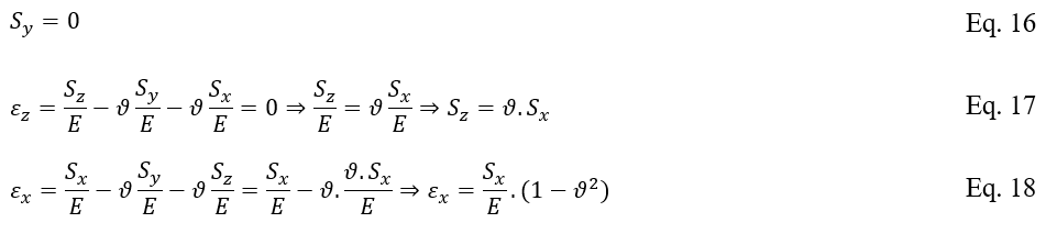
The result shows that for a laterally restricted beam, the εX is smaller than εX predicted by Hook’s low by a factor of (1-v2). In other words, a laterally restricted beam is stiffer than a free beam. To compensate for the reduction in strain, the flexural rigidity (EI) must be increased by a factor 1/(1-v2). This can be achieved by increasing either E or I. For simplicity, it is recommended to increase the moment of inertia, I. Thus, for the rectangular cross-section of a beam with unit width (b=1), the moment of inertia is as follows:
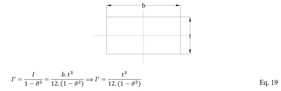
By combining the Eqs. 15 and 19, the β is as follows:

If the value of v is assumed to be 0.3, then the β=1.285/√(r.t)
Effective Width of Discontinuity Area
Once the β is evaluated, another key parameter, known as the effective width (x), must be determined, for example when reinforcement is required. The effect of discontinuity decreases exponentially as the distance from the discontinuity increases. It reduces rapidly but never completely disappears. Thus, an effective zone is considered to account for the discontinuity area.
Owing to the uncertainty regarding the effective zone, each situation requires a specific method for defining an appropriate effective zone. For example, one suitable criterion is the distance where the shear force becomes less than 20% of the maximum shear force, or the bending moment becomes less than the 21% of the maximum bending moment.
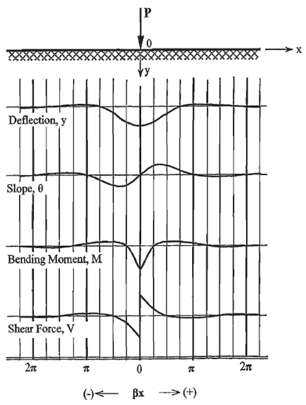
Figure 4 shows the deflection, slope, bending moment and shear force along the beam in terms of the dimensionless parameter βx (x is the distance from the discontinuity point). It should be noted that the P curves reflect only the general shapes.
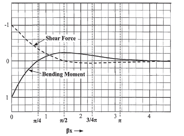
With respect to the symmetry of the beam and the importance of the shear force and bending moment, Figure 5 provides an enlarged view of the attenuation. Based on this figure, the magnitude of the shear force becomes less than 20% of its maximum value when βx is more than 1, and the bending moment becomes less than 21% of its maximum value when βx is more than (pi)/2.
References
- Pipe Stress Engineering – L.C. Peng and T.L. Peng